UPS System
UPS and critical power system applications are focused on delivering quality power, whether originating from an electric utility or from internal energy storage, on an assured, 24/7 basis.
Datacenter should have reliable device to maintain the business continuity without any disruption. A UPS is usually required to provide stable power to sensitive active and passive equipment, and it can become single point of failure that affect multiple servers and business continuity disruption can be huge. So, resilience should be considered while planning the UPS for datacenter.
The primary concern of UPS system design for Class F3 and F4 systems is the maintenance of critical power services while accommodating known failures or allowing for safe and logical preventive maintenance.
Select a UPS that supports multiple power inputs, allowing two different sources to power the UPS unit. If one utility line fails, power from the other line can run the load and keep the UPS charged.
The Uptime Institute regards electricity from utility service providers as an unreliable source of power. Therefore, Tier 3 data center specifications require that the data center should have diesel generators as a backup for the utility power supply.
An automatic transfer switch (ATS) automatically should transfer the control to backup generator if the utility power supply goes down.
The Tier 3 data center specifications mandate two ATSs connected in parallel to ensure redundancy and concurrent maintainability.
Tier 3 data center specifications require the diesel generators to have a minimum of 12 hours of fuel supply as reserves. Redundancy can be achieved by having two tanks, each with 12 hours of fuel. In this case, concurrent maintainability can be ensured using two or more fuel pipes for the tanks. Fuel pipes can then be maintained without affecting flow of fuel to the generators.
Redundancy and concurrent availability can be achieved using separate power distribution panels for each ATS. This is because connecting two ATSs to a panel will necessitate bringing down both ATS units during panel maintenance or replacement.
The Tier 3 data center specifications require two or more power lines between each ATS and power distribution panel to ensure redundancy and concurrent maintainability.
Each power distribution panel and UPS should also have two or more lines for the same purpose.
Power from the distribution panel is used by the UPS and supplied to the power distribution boxes for server racks as well as a network infrastructure. For example, if a 20 KVA UPS is required for a data center, redundancy can be achieved by deploying two 20 KVA UPS or four 7 KVA UPS units. Redundancy can even be achieved with five 5 KVA UPS units.
The Tier 3 data center specifications require that each UPS be connected to just a single distribution box for redundancy and concurrent maintainability. This ensures that only a single power distribution circuit goes down, in case of a UPS failure or maintenance.
Each server rack must have two power distribution boxes in order to conform to Tier 3 data center specifications. The servers in each rack should have dual power supply features so that they can connect to the power distribution boxes.
A static switch can be used for devices which lack dual power mode features. This switch takes in supply from both power distribution boxes and gives a single output.
The static switch can transfer from a power distribution box to another in case of failures, within a few milliseconds.
A data center built according to Tier 3 data center specifications should satisfy two key requirements: redundancy and concurrent maintainability. It requires at least n+1 redundancy as well as concurrent maintainability for all power and cooling components and distribution systems.
A component’s lack of availability due to failure (or maintenance) should not affect the infrastructure’s
normal functioning.
Class F3 Model provides multiple power paths as close to the critical load as possible and Class F4 Model include different number of UPS power plants versus the number of UPS Power delivery path.
The static bypass, the maintenance bypass, the output breaker, and any load bank testing connections can all have a direct impact on the maintenance and failure response of the UPS system.
Bypass configurations can affect UPS functionality as follows:
- Combining maintenance bypass and static bypass paths from a single input feeder will typically result in a lower Class because it reduces the ability to remove a module or system without interrupting the service to the downstream critical loads.
- Load bank connections that are independent of the UPS output source can contribute to a high Class because they allow for testing without interrupting the service to the downstream critical loads.
- Locating circuit breakers on the collector bus or on the output bus of paralleled UPS systems rather than Making them internal to a power module will contribute to a high Class by allowing a module to be removed from the service without shutting down the entire system. These are also known as isolation breakers.
- The presence of a maintenance bypass will allow for the removal or testing of a UPS module or for the replacement of a static switch in the event of a catastrophic failure. This has a dramatic effect on the mean time to repair (MTTR).
Maintenance bypass is mandatory for all Class F3 and F4 applications and for system control cabinets.
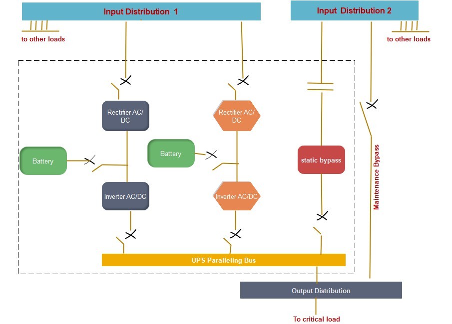
When the input to the rectifier and the static bypass originate from one bus (Input Distribution 1) and the maintenance bypass originates from a separate bus (Input Distribution 2), the critical load shall be transferred without interruption or disturbance to an isolated source, either utility or generator, depending on the design, while the UPS is repaired or tested.
When other loads are connected to the bus that support either the rectifier and static bypass (Input Distribution 1) or the maintenance bypass (Input Distribution 2), the designer shall also consider how any disturbance on the input bus could affect the critical load while operating in this mode and (how to minimize the disturbance). This type of design, including disturbances may be caused by:
- Testing of the UPS
- Testing of other loads connected to the same bus
- Turning on and off other loads connected to the same bus
- Fault conditions
Inputs to the static bypass and maintenance bypass shall not be derived from separate sources unless the two sources are synchronized in phase and frequency. Lack of synchronization will result in an unreliable design that should require open transition (i.e., shut down the loads and then restart from the alternate source.
Note that synchronization of sources is difficult because load imbalances and phase shifts (such as transformers introduced downstream) can force circuits out of synchronization. The best practice is to power both the static bypass and the maintenance bypasses from the same source.
The UPS system static bypass and maintenance bypass designs should consider using the same source or type of source for the closed transition transfer mechanisms.
This would require the power module inputs, static bypass input, and the maintenance bypass input to be synchronized to the same source.
Depending upon the configuration, some UPS could be exempted from this rule when the static bypass input and the output of the UPS are synchronized. For example, input to power module inputs could be fed from utility 480 VAC wye source “A” while the static bypass and maintenance bypass could be fed from utility (or generator) 480 VAC wye source “B”.
Other UPS configurations may have the maintenance bypass external to the UPS system to enable the UPS to be taken off-line for maintenance or replacement. It is acceptable to have the maintenance bypass internal to the UPS system in a Catcher system since the Standby UPS system can function as the external alternate path in the event the UPS system needs to be taken off-line for maintenance or replacement.
Attention shall be paid with respect to the configuration of disconnects external and internal to the UPS
system to enable maintenance of rectifiers, inverters, or static bypass components in a safe manner.
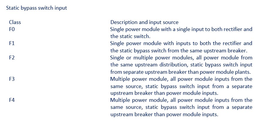
A dedicated input to the static switch that is separate from the rectifier input allows the critical load to further sustain faults that could be associated with the rectifier. In Class F0 and Class F1 applications, a single source of input power for both the rectifier and the static bypass is permitted.
No Comments