Building Ground (Electrode) Ring
A building ground electrode ring shall be installed for facilities where a lightning protection system is installed or where there are multiple power service entrance locations along the periphery of the facility.
As required by local codes and standards, the ground ring shall be bonded to structural metal at every other column or more often. Concrete-encased electrodes (also known as Ufer electrodes) shall be used in new construction as a method of supplementing the grounding electrode system.
Concrete-encased electrodes improve the effectiveness of the grounding electrode system because of concrete having hygroscopic properties and by providing a much larger surface area in direct contact with the surrounding soil:
- Concrete-encased electrodes shall be encased by at least 51 mm (2 in) of concrete, located within and near the bottom of a concrete foundation or footing that is in direct contact with the earth.
- Concrete-encased electrodes shall be at least 6 m (19.7 ft) of bare copper conductor not smaller than 21.1 mm2 (4 AWG) or at least 6 m (19.7 ft) of one or more bare or zinc galvanized or other conductive coated steel reinforcing bars or rods at least 12.7 mm (0.5 in) in diameter.
- Concrete-encased electrodes shall be bonded to any other grounding electrode system at the site.
- This building grounding system shall be directly bonded to all major power distribution equipment, including all switchgear, generators, UPS systems, and transformers, as well as to the telecommunications systems and lightning protection system. The facility shall possess a building electrical main ground bus (MGB) where all the large-load feeder facility grounds terminate. This is the location, coupled with the telecommunications main grounding bus bar (TMGB), where the grounding system can be validated for both continuity and impedance.
A building ground electrode ring should be installed for all facilities.
Single or triplex ground rod fields as the only earthling vehicle are not adequate for a critical facility.
The direct burial connections should meet appropriate electrical testing requirements as set out in the applicable standards and codes to ensure durability.
Designs may vary according to the site parameters such as available real estate, earth resistivity, frost line level, and the depth of the water table.
Ground bus bars should be placed to facilitate bonding and visual inspection.
The ground ring should be 107 mm2 (4/0 AWG) minimum bare copper wire buried a minimum 800 mm (30 in) deep and a minimum 1 m (3 ft.) from the building wall. For larger sizes, stranded conductors are recommended.
Ground rings encircling buildings should be installed just beyond the roof drip line.
The size of the ground ring conductor is recommended to be the same as the largest size required by the Rwanda Standards Board for a grounding electrode conductor to promote the accomplishment of intersystem bonding.
The ground rods should be connected to the ground ring. Typical ground rods are 19 mm by 3 m (3/4 in by 10 ft) copper-clad steel ground rods spaced every 6 to 12 m (20 to 40 ft) along the perimeter ground loop.
Test wells for the building ground electrode ring should be provided at the four corners of the loop.
The common grounding electrode system should not exceed 5 ohms to true earth ground as measured by the fall of potential method (IEEE 81). As noted in the NEC, IEEE 1100, and IEEE142, common bonding of different systems plays a crucial role along with grounding.
Supplementary bonding and grounding methods are those provided in addition to the bonding and grounding measures typically required by the applicable electrical safety codes and product safety standards.
Supplementary bonding and grounding methods are intended to improve facility and equipment performance related to bonding and grounding. Examples of supplementary bonding and grounding entities may include metallic raceways, racks and cable trays; under the raised floor or above the cabinet and rack metallic grid work; metal plates and metal sheets; multiple bonding conductors from equipment to a grounding/bonding structure, etc.
An integral part of the bonding and grounding network in the access floor area or any critical environment is the grounding of the IT support equipment and static discharge management during ongoing operations. This includes the connection of a cabinet of ITE chassis to the mesh-BN, connections between various IT systems and cabinets, and personal grounding checks and static charge dissipation.
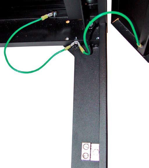
Rack Connections to the Mesh-BN It is common for cabinets to be physically connected for structural integrity, and they also may be logically, virtually, or network connected, acting as an integral platform.
This is achieved by the manufacturer assembling the cabinet or rack in such a way that there is electrical continuity throughout its structural members. For welded racks, the welded construction serves as the method of bonding the structural members of the rack together.
All adjacent cabinets and systems should be bonded in order to form grounding continuity throughout the rack structure itself.
Electrical continuity cannot be assumed using a nut and bolt connections used to build or stabilize equipment cabinets and racks.
Bolts, nuts, and screws used for rack assembly may not be specifically designed for grounding purposes, and unless grounding bonding jumpers are installed, do not assume electrical continuity for the cabinet lineup.
Most cabinets and racks are painted, and as paint is nonconductive, this negates any attempt to accomplish desired grounding. Therefore, paint or cabinet coating must be removed in the bonding area for a proper bond to be formed.
Most power is routed over the top or bottom of the rack. Without a reliable bond of all four sides of the rack, a safety hazard exists from potential contact with live feeds.
Personal Grounding and Static Discharge
Electrostatic discharge (ESD) is the spontaneous transfer of electrostatic charge. The charge flows through a spark (static discharge) between two bodies at different electrostatic potentials as they approach each other.
Electrostatic discharge (ESD) may cause permanent damage or intermittent malfunction of networking hardware.
Anyone that touches network equipment or network cabling becomes a potential source of ESD as it relates to telecommunications equipment.
Network cabling that has been installed but not connected may become charged when these cables are un-spooled and slid over carpet or other surface that contributes to the buildup of ESD.
The charged cabling may become a source of ESD to the telecommunications equipment to which it connects. Charged cabling should be discharged to an earth ground prior to connection to network equipment.
ESD charges may remain for some time, especially in dry conditions.
Factors affecting ESD charge retention include:
- Cable design
- Dielectric materials
- Humidity
- Installation practices
Low humidity and static-generating building materials are the primary causes of ESD.
There should be no significant ESD charge retention difference between types of telecommunication cabling as all cables have a nearly identical ability to acquire a static charge.
It is important to follow all ESD specifications and guidelines provided by the applicable network equipment manufacturer.
Mitigation techniques, such as anti-static flooring and humidity control are important for critical installations.
The use of static discharge wrist straps when working on or installing network or computer hardware is
specified in most manufacturers’ installation guidelines.
Wrist strap ports should be attached to the rack by a means that ensures electrical continuity to ground. Pedestrian static discharge mats may be required for certain access floor environments or spaces with
standard resistance flooring.
No Comments