Telecommunications Cabling Infrastructure Classes
For the telecommunications cabling infrastructure reliability classes, the corresponding class designation
is prefaced with a “C” to identify it represents the “cabling infrastructure” reliability criteria.
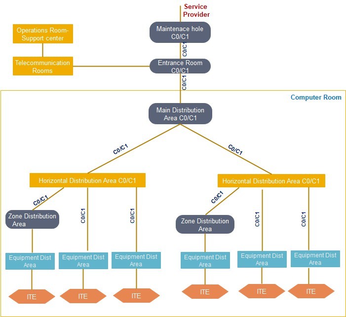
Class C0 and C1 Telecommunications Infrastructure
A Class C0 or C1 telecommunications cabling infrastructure is a single path cabling infrastructure. The cross-connect fields throughout the data center support a single path, non-redundant network architecture.
Entrance Pathways: Single path, multiple conduits from property line to
ER-Entrance Room: One ER accommodates a service provider
Main Distribution Area:
One MDA supports all core equipment
Intermediate Distribution Area
Each HDA supported by a single MDA or IDA Horizontal Distribution Area:
Non-redundant HDA to support any intermediary switching equipment and horizontal cross-connect fields, multiple HDAs may be required to support port counts and distance limitations within large computer rooms.
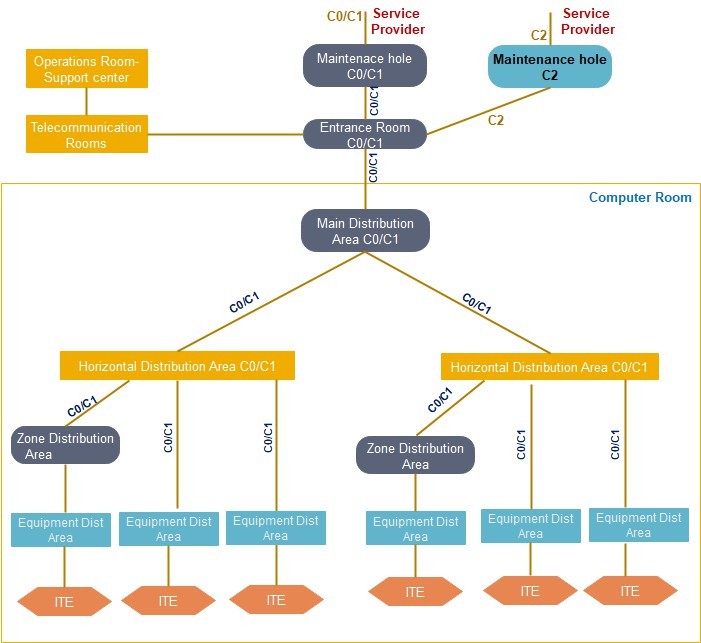
Class C2 Telecommunications Infrastructure
A Class C2 telecommunications cabling infrastructure is a single path cabling infrastructure. The cross- connect fields throughout the data center support a single path, non-redundant network architecture. It contains redundant entrance pathways to support, at a minimum, a single link from two providers or ringed topology from one provider.
Entrance Pathways: Redundant and diverse multi-path, each path with multiple conduits from property line to ER.
Entrance Room: One ER accommodates a service provider(s) Main Distribution Area: One MDA supports all core equipment
Intermediate Distribution Area Each HDA supported by a single MDA or IDA
Horizontal Distribution Area: Non-redundant HDA to support any intermediary switching equipment and
horizontal cross-connect fields, multiple HDAs may be required to support port counts and distance limitations within large computer rooms.
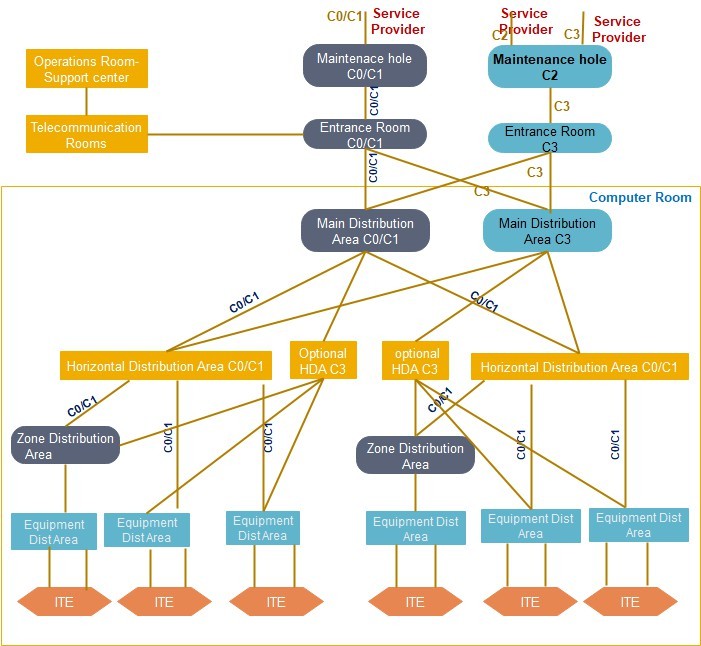
Class C3 Telecommunications Infrastructure
A Class C3 telecommunications cabling infrastructure is a redundant path cabling infrastructure that has redundant cross-connect fields for all backbone network cabling.
The redundant backbone cabling is intended to support a redundant network.
Physically separated redundant horizontal cross-connects and a redundant horizontal cabling to equipment cabinets (EDAs) is also recommended.
Physical separation between redundant MDAs, IDAs, or HDAs may minimize common modes of failure that may be present within the supporting critical infrastructure (e.g., failure of the sprinkler system, raised floor system, cabling pathway system, grounding system).
Physical separation may also minimize failure because of any event caused by human error or component failure, which is not contained within an MDA or HDA cabinet, thereby exposing adjacent cabinets to risk of failure.
Having redundant distributors and cabling may increase operational complexity.
Entrance Pathways: Redundant and diverse multi-path, each path with multiple conduits from property line to each ER.
Entrance Room: Two ERs to support multiple service providers, providing physical separation between
Redundant provider and edge equipment.
Main Distribution Area: MDAs support the main cross-connect (MC) and backbone network equipment. Redundant MDAs should be physically separated.
Intermediate Distribution Area IDAs support the intermediate cross-connect (IC) and possibly backbone network equipment. Redundant IDAs should be physically separated.
Horizontal Distribution Area: HDAs support horizontal cross-connects and may support access layer
switches.
Equipment cabinets (EDAs) should (but are not required to) have horizontal cabling to two different, physically separated HDAs.
Class C4 Telecommunications Infrastructure
A Class C4 telecommunications infrastructure is a redundant path cabling infrastructure that has redundant cross-connect fields throughout data center network to support redundant network architecture. It contains redundant entrance facilities to support multiple network service provider topologies.
Physical separation between redundant MDAs or HDAs is required to minimize common modes of failure that may be present within the supporting critical infrastructure (e.g., failure of; sprinkler system, raised floor system, cabling infrastructure pathway system, grounding system, electrical distribution system) or any event caused by human error or component failure, which is not contained within one MDA or HDA cabinet, thereby exposing adjacent cabinets to risk of failure as well.
Entrance Pathways: Redundant and diverse multi-path, each path with multiple conduits from property line to each ER
Entrance Room: Two ERs to support multiple service providers, providing physical separation between redundant providers edge equipment.
Main Distribution Area: Two MDAs to support redundant core equipment. Physical separation between redundant MDAs is required to minimize common modes of failure that may be present within the supporting critical infrastructure.
Intermediate Distribution Area Redundant physically separated IDAs. If an HDA has backbone cabling to
IDAs, it must be supported by diversely routed backbone cabling to two physically separated IDAs.
Horizontal Distribution Area: Redundant HDAs to support any intermediary redundant switching equipment and horizontal cross-connect fields, additional HDAs may be required on both the “A” and
“B” network fabric to support increased port counts and distance limitations within large computer rooms.
Physical separation between redundant HDAs is required to minimize computer common modes of failure that may be present within the supporting critical infrastructure

No Comments