Data center network cabling design
The datacenter cabling infrastructure layer contains, and the Data center spaces dedicated to supporting the telecommunications cabling system and related equipment are listed below. These spaces include:
- Entrance Room (ER)
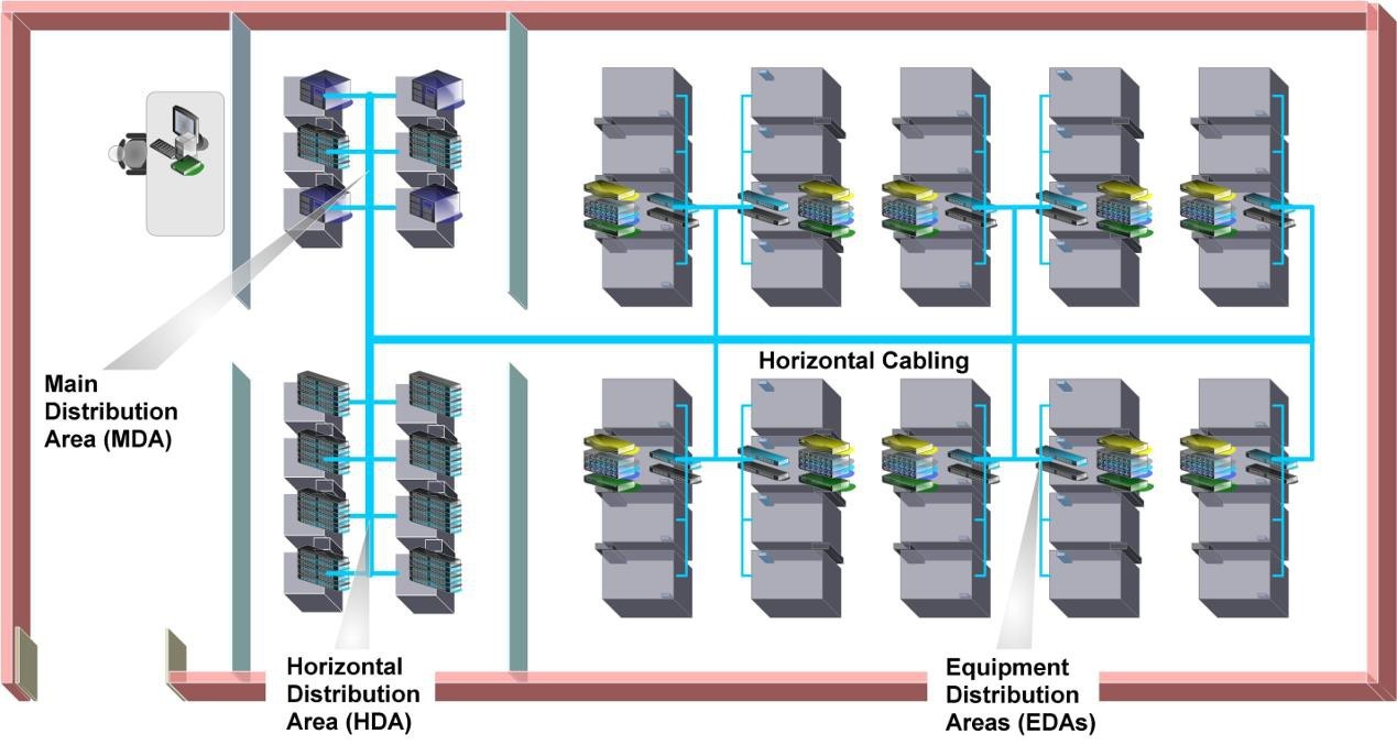
- Main Distribution Area (MDA)
- Horizontal Distribution Area (HDA)
- Equipment Distribution Area (EDA)
- Zone distribution area (ZDA)
Data center telecommunications spaces such as the MDA and entrance room(s) shall be sized for full data center occupancy, including all anticipated expansions and planned applications.
All data center spaces for telecommunications shall have the same mechanical and electrical redundancy as the computer room(s). (Or even opposite) sides of the building.
Conduit duct banks and their associated maintenance holes and other pathways from the access provider central offices and service provider point-of-presences to the building’s entrance facilities should be separated by at least 20 m (66 ft.) along their entire routes.
A conduit duct bank with appropriately placed maintenance holes that surrounds a data center and incorporates multiple building entrance facilities should be considered for the data center.
At least one conduit for replacement cables should be set aside for each internal and entrance pathway to facilitate rapid replacement of cables.
The use of inner duct, either conventional or fabric, is recommended aiding in cable management and increased utilization of available conduit space.
Entrance Rooms
Access providers that serve the building shall be contacted to ascertain the point(s) of entry to the property and the requirements for their telecommunications cabling, terminations, and equipment.
Class C2 and higher data centers shall have diverse entrance facilities, preferably with route diversity from the data center to different access providers.
A Class C2 data center may be served from multiple central offices and multiple service provider point-of- presences that enter the property at different locations.
The location of each building entrance facility shall be coordinated with routing of access provider pathways as well as internal pathways and shall not conflict with the location of other building facilities such as power, gas, and water.
Each building point-of-entry supporting an access provider’s outside plant facilities should be located on different (or even opposite) sides of the building.
Conduit duct banks and their associated maintenance holes and other pathways from the access provider central offices and service provider point-of-presences to the building’s entrance facilities should be separated by at least 20 m (66 ft.) along their entire routes.
A conduit duct bank with appropriately placed maintenance holes that surrounds a data center and incorporates multiple building entrance facilities should be considered for the data center.
At least one conduit for replacement cables should be set aside for each internal and entrance pathway to facilitate rapid replacement of cables. The use of inner duct, either conventional or fabric, is recommended aiding in cable management and increased utilization of available conduit space.
When using multiple entrance rooms, entrance rooms should be at least 20 m (66 ft) apart and be in separate fire protection zones. The two entrance rooms should not share power distribution units or air conditioning equipment.
Telecommunications entrance cabling for data centers should not be routed through a common equipment room unless cabling is segregated from common access via conduit or other means.
Entrance rooms should be outside the computer room - to improve security. However, they may be placed in the computer room or consolidated with the main distribution area if cabling distances for circuits is an issue, security is not an issue, or other security measures are used to ensure security (such as escorting and monitoring the activities of all technicians in the computer room).
Main Distribution Area (MDA)
The MDA includes the main cross-connect (MC), which is the central point of distribution for the data center structured cabling system. The main cross-connect is called the main distributor (MD)
Equipment typically located in the MDA includes:
- Core routers
- Core, spine, or interconnection layer LAN and SAN switches
- High-performance computing switches
- PBX or voice gateways
- T-3 (M13) multiplexers
The MDA may serve one or more IDAs, HDAs, and EDAs within the data center and one or more telecommunications rooms (TRs) located outside the computer room space to support office spaces, operations center, and other external support rooms.
All data center shall have at least one MDA. A second MDA shall be provided to meet the availability requirements of the telecommunications infrastructure (e.g., Class C4). If two MDAs are present, both shall meet all requirements of the MDA as specified in the applicable data center standard.
Access provider provisioning equipment (e.g., M13 multiplexers) may be in the MDA rather than in the entrance room to avoid the need for a second entrance room because of circuit distance restrictions.
A second MDA is recommended in Class C3 data centers. Each MDA should have fully diverse cable routes to access multiple entry points so that no single point of failure exists within the site.
When utilizing two MDAs, the MDAs should:
- Have core routers and switches distributed between the MDAs
- Distribute circuits between the two spaces
- Be in different fire protection zones
- Be served by different power distribution units and air conditioning equipment
Intermediate Distribution Area (IDA)
The intermediate distribution area (IDA) is the space that supports the intermediate cross-connect. The intermediate cross-connect is called the intermediate distributor.
It may be used to provide a second level cabling subsystem in data centers too large to be accommodated with only MDAs and HDAs. The IDA is optional and may include active equipment such as LAN and SAN switches.
The IDA may include the horizontal cross-connect (TIA) or zone distributor (ISO/CENELEC) for equipment areas served directly from the IDA.
The IDA may be inside the computer room but can be located in a dedicated room or a secure cage within the computer room for additional security.
Horizontal Distribution Area (HDA)
The HDA is used to serve equipment not supported by a horizontal cross-connect (HC) or zone distributor
(ZD) in an IDA or MDA. The HDA is the distribution point for cabling to the EDAs. Equipment typically located in the HDA includes:
- LAN switches
- SAN switches
- Keyboard/video/mouse (KVM) switches
This equipment is used to provide network connectivity to the end equipment located in the EDAs. A small data center may not require any HDAs as the entire data center may be able to be supported from the MDA. A typical data center will have several HDAs.
Zone Distribution Area (ZDA)
The ZDA is an optional interconnection point within the horizontal cabling located between the HDA and the EDA to allow frequent reconfiguration and added flexibility.
The consolidation point in the ZDA is called the local distribution point or LDP in CENELEC EN 50173-5 and in ISO/IEC 24764.
Horizontal cabling shall contain no more than one ZDA between the HC in the HDA and the mechanical termination in the EDA.
The zone distribution area may also serve as a zone outlet for nearby equipment in the computer room.
Equipment Distribution Area (EDA)
The EDA is the space allocated for end equipment, including all forms of telecommunications equipment
(e.g., computer equipment, telephony equipment).
EDA areas shall not serve the purposes of an entrance room, MDA, IDA, or HDA.
1 Comment
Excellent article on planning and designing efficient cabling infrastructure for modern networks. Reliable <a href="https://www.structurecabling.ae/services/fiber-optic-cabling-in-dubai-uae/">Fiber Optic Cabling in Dubai </a> helps organizations improve connectivity, support high-speed communication, and maintain scalable systems for future technology growth.