Mechanical and Cooling System
Datacenters are critical, energy-hungry infrastructures that operate around the clock. They provide computing functions that are vital to the daily operations of top economic, scientific, and technological organizations around the world. Cooling must be one of the primary concerns of a Datacenter designer.
Effective heat removal from the datacenter equipment requires attention to the direction of airflow. An important part of thermal management of air-cooled electronic equipment is air management. All HVAC systems are not compatible with all data center, so the designer should select the appropriate HVAC System for specific datacenter. It is necessary to choose appropriate HVAC (Heating-Ventilation-Air Conditioning) system and equipment used is made based on many factors. Below a list of few factors to be considered while choosing datacenter cooling,
- Room size
- Overall cooling density (watts per square meter or watts per square foot), which is established by the maximum kW load for the computer equipment used in the electrical design. Cooling load should match actual operating load as opposed to nameplate load.
- kW per cabinet or module
- Number and capacity of HVAC units required to meet load and redundancy criteria and their location in the space relative to computer equipment layout
- Room location relative to mechanical support spaces
- Room location in the building relative to outdoors
- Ceiling height
- Absence or presence of access floor
- Access floor height
- Future expansion needs
- Reliability requirements
- Available maintenance personnel
- Local climate
Provide dual cooling and heating systems utilizing down flow discharge modular cooling units for most effective systems.
Design should consider maintaining a consistent temperature and humidity to counteract the hot dry air created by your equipment.
Design should consider that equipment density is constantly rising and along with it the heat and energy loads.
Ensure that you have adequate capacity for the future power and HVAC needs of your facility and potential future expansion without disrupting the business operations.
All environmental controls should be monitored with logging, trend projection and alarm notification. Ensure that the location of equipment is critical, and the type must provide an easy but secure access for
maintenance.
Ensure that the capability in facility design to replace all pieces of equipment without affecting operations of the facility.
Air conditioners and air handlers
The most common types are air conditioner (AC) or computer room air handler (CRAH) units that blow cold air in the required direction to remove hot air from the surrounding area.
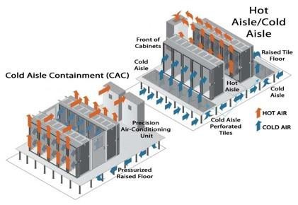
Hot aisle/cold aisle
The cold air (or aisle) is passed to the front of the server racks and the hot air comes out of the rear side of the racks. The main goal here is to manage the airflow in order to conserve energy and reduce cooling cost.
Hot aisle/cold aisle containment
Containment of the hot/cold aisles is done mainly to separate the cold and hot air within the room and remove hot air from cabinets. The image below shows detailed airflow movement of cold and hot containment individually.
The total of all server airflows in that row represents the total airflow through the racks from the cold aisle to the hot aisle.
This is not the same as the volume of air that must be supplied to the cold aisle by the HVAC system.
The HVAC system must supply more air since the temperature difference produced by the HVAC equipment will generally be lower than the temperature rise through the electronics equipment because of bypass air waste and related mixing of supply air and return air.
HVAC systems and cooling equipment must always be selected using a holistic approach. The choice of air distribution method should never be considered without evaluating other significant factors, such as whether or not an access floor is used, the return air path, location of CRAC units or air handling equipment relative to server racks, orientation of hot/cold aisles, ceiling height, methods for humidity control, and provisions for future expansion, to name just a few.
Each choice affects the others, and the overall performance of the data center cooling system will be dictated by the entire package of decisions.
It is recommended that to design the datacenter with access floor which assist to manage the hot aisle and cold aisle
Airflow in the typical data center consists of two flow loops:
- CRAC units (a few big fans) circulate air within the entire room.
- Servers (many little fans) circulate air between cold and hot aisles.
Each of the two airflow loops described above operates with a different temperature difference between inlet and supply. However, the energy must balance between the two; all the heat rejected from the servers must be further rejected in the CRAC unit.
The type of air delivery method through an access flooring system should be consistent.
Do not mix perforated tiles with supply air grilles as the differences in flow/pressure drop characteristics will result in an inconsistent and unpredictable performance.
Large, relatively unobstructed openings in the access floor can have significant adverse effects on the underfloor pressurization and should be avoided as the larger the opening, the smaller the pressure drop corresponding to a cubic meters or feet per minute
Air takes the path of least resistance; large openings will starve the perforated floor tiles. Large means any opening that is large relative to a single perforation in an access floor tile. Many (relatively) small openings can begin to look to the HVAC system like a few very large openings.
An access floor system provides a flexible method of delivering cooling to data centers, allowing for numerous configurations.
Perforated panels can readily be moved to accommodate high heat load areas.
Floor height should be selected based on the combined needs for airflow, power distribution, network/communications cabling, and chilled water distribution, if used.
Access floor heights greater than 900 mm (36 in) introduce additional cost to the flooring system, may require special considerations for access and safety, and do not significantly enhance the uniformity of air distribution below power densities of 1350 W/m2 (125 W/f2).
For data centers with power densities in the 1610 to 2150 W/m2 (150 to 200 W/f2) range, a 1060 mm (42 in) access floor depth should be considered.
Chilled air should always be delivered into the cold aisle in front of the cabinets and not be delivered directly into the bottom of the cabinet. There are three main reasons for this:
Openings provided below the racks for this purpose will generally be large compared to the tile perforations.
- Some air will bypass out through the back of the rack into the hot aisle.
- Air supplied directly into the bottom of a cabinet may be significantly below the minimum temperature.
- CRAC unit discharge air temperature is typically in the 13 to 16 °C (55 to 60 °F) range, and 80% to 90% RH at that temperature.
- With Underfloor distribution, the air coming out of the perforated tiles will usually be below 20 °C (68 °F).
Room temperature measurement points should be selected in conformance to ASHRAE Thermal
Guidelines:
Temperature measurement sensors should be regularly calibrated.
A significant difficulty with temperature and humidity measurement point locations is the physical installation in meaningful locations.
Sensors typically must be mounted on a fixed surface, making the mid-aisle 1500 mm (60 in) above floor locations impractical for permanently installed devices.
Temperature and humidity sensors furnished with CRAC units are factory installed in the units at their inlet and do not indicate the conditions of the air at the computer equipment inlets.
Temperature-measuring points should ideally mimic the equipment inlet conditions since these conditions define the equipment comfort.
Floor plenums should be as airtight as possible relative to adjacent spaces and cleaned prior to being put into use.
Overhead ductwork must be closely coordinated with lighting, sprinklers, and power or network cabling in data centers where these utilities are not located below an access floor.
Overhead ducts wider than 1200 mm (48 in) will require sprinkler heads to be located below the ductwork. Cabinets and racks shall be arranged in rows with fronts of cabinets/racks facing each other in a row to
create hot and cold aisles.
Equipment should be placed in cabinets and racks with cold air intake at the front of the cabinet or rack and hot air exhaust out the back, top, or both.
Reversing the equipment in the rack will disrupt the proper functioning of hot and cold aisles.
Blank panels should be installed in unused cabinet and rack spaces to improve the functioning of hot and cold aisles.
When placed on an access floor, cabinets and racks shall be arranged to permit tiles in the front and rear of the cabinets and racks to be lifted.
Cabinets should be aligned with either the front or rear edge along the edge of the floor tile per TIA-942- A.
Cabinet size, location for air entry, location for cable entries, and access to front and rear should be planned for consistency according to ETSI EN 300-019.
CRAC units should be in the hot aisle path when the return air path is the free space in the room.
Return air should be positioned to capture the highest heat concentration such as return air intakes directly over the hot aisles or directly over equipment producing the highest heat.
Capturing the heat with return grilles and not entraining it in the supply air should be the goal of return and supply layouts.
When using a return air system to reduce recirculation, supply air temperature must be controlled to very near the lowest acceptable equipment inlet temperature.
A ceiling height of at least 3 m (10 ft.) above the access floor will allow for an effective hot air area above cabinets and racks and optimize the return air path. Rooms with high-density cooling loads should consider ceilings higher than 3 m (10 ft.).
The cold aisle plenum space should remain unobstructed by raceways in conformance to TIA-942-A. Floor tile cutouts for cable egress to cabinets and damping around cables should conform to TIA-942-A. When overhead cable systems are used in lieu of or in addition to underfloor cabling, placement and
grouping of cable should be planned to minimize the effects on return air.
Obstructions in the return air path could contribute to higher levels of hot air recirculation to the cold aisles, depending on the configuration of the cable system relative to the rack layout.
HVAC availability and redundant power access should conform to the requirements of the Class that best satisfies the reliability goals of the enterprise.
Providing CRAC units and other mechanical cooling equipment with dual power sources to ensure continuous operation if one source of power is lost is to be considered for Class F3 and Class F4 but is not mandatory under the requirements of this standard and is not required for Class F2 or lower facilities.
No Comments