Bonding, Grounding, Lightning Protection, and Surge Suppression
The comprehensive electrical protection required for the critical facility is achieved using a system approach to integrate lightning protection, overvoltage and surge suppression, bonding and grounding.
Grounding is addressed in three sections: electrical distribution, PDU, and within the computer room. Electrical system grounding is consistently misunderstood and, for most facilities, not adequately maintained, changed or integrated to the ITE loads that it serves.
It is the intent of this standard to provide a bonding and grounding system that substantially equalizes any no transient potential differences so that all the enclosures, raceways, and all bonded metal found in the computer room are effectively at the same ground potential (substantially equalized).
Bonding and grounding of data centers relates most specifically to maintaining the facility’s common electrical bonding and grounding system along with any desired supplementary bonding and grounding for the ITE.
Bonding and grounding also address vital issues such as harmonic current management and fault current mitigation.
Bonding and grounding also integrate voltage transient suppression by the application of SPD (surge protection device) systems as well as lightning protection systems.
The bonding and grounding system are one of the few electrical systems completely systemic to the entire critical facility.
If properly organized and installed, the ground system is essentially a radial system from the electrical service entrance. There are a few subtleties for critical facilities that vary from other buildings.
Where generators are not treated as separately derived sources, neutrals and grounds are routed with the associated phase wiring and carried back (without being switched) to the main service and terminated on the main service’s neutral and ground buses.
Where generators are treated as separately derived sources, grounds are carried back to the main service and terminated on the main services ground bus.
Data center bonding and grounding addresses all bonding and grounding work within the critical environment.
These systems include:
- The separately derived system at the PDU
- Ground path to the load
- Critical environment grounding—supplementary at the ITE
- ITE bonding and grounding
- Personal grounding and static discharge.
Bonding and grounding for a data center involve several entities such as:
- A common grounding electrode system (GES) for the building, involving the intersystem bonding of a:
– Grounding electrode system for the electrical power
– Grounding electrode system for the lightning protection system (LPS)
– Grounding electrode system for the telecommunications service provider cables and protectors - Grounding electrode conductors for solidly grounding each power service entrance
- Grounding electrode conductors for solidly grounding each separately derived power source such as an engine-generator for standby power
- Grounding electrode conductors for solidly grounding each telecommunications service entrance
Bonding and grounding infrastructure for telecommunications utilizing components such as the BCT, TMGB, TBB, TGB, and GE as described in TIA-607-B
- Equipment grounding conductor for power distribution from the service/source to the load
- Structural metal
- Grounding conductors such as the down conductors for an LPS and SPDs
- The common bonding network (CBN) within the building
- Supplemental bonding and grounding structures for electronic equipment such as:
– Mesh-bonding network (mesh-BN)
– Isolated bonding network (IBN)
– Supplementary bonding grid.
The common bonding network (CBN) is the set of metallic components that are intentionally or incidentally interconnected to form the bonding network (a mesh) in a building. The CBN always has a mesh topology and connects to the grounding electrode system via one or more grounding conductors.
Serving power systems and electronic equipment bonding and grounding primarily involves the serving power source and the power distribution to the IT and other electronic equipment.
This primary level of bonding and grounding is required to be in accordance with the NRTL product safety listing of the power system and the electronic equipment (load).
The entities of concern are the grounding electrode conductor (system) and equipment grounding
(bonding) conductor (or green wire).
These dedicated circuit conductors are required for the safe operation of the equipment, including any ground faults.
In some instances, equipment may be designed as “double insulated,” whereby the NRTL requirements for the equipment grounding conductor may be eliminated (e.g., a two-prong plug or receptacle). Although data center electrical and electronic equipment may be considered “grounded” according to its NRTL requirements, supplementary bonding and grounding are recommended.
High-resistance/impedance grounding (HRG) systems can be used in lieu of solidly grounded systems. HRGs are typically designed to limit a ground fault current to 10 Amps or less. The advantages of using HRGs are:
- Safety enhancements because of mitigation of phase-to-ground fault currents
- Operational enhancements because of reduction of ground fault current trips
- Reduced cost because of the elimination of four-wire feeders
The HRGS (High Resistance Grounding System) are installed at the service transformer. They function down to the first separately derived source in the distribution system. Where used for ITE installations, consideration should be given to any impact on the resistance/impedance of the grounding systems.
HRGs (High Resistance Grounding System) may influence the level of electrical noise versus earth ground at higher frequencies such as for filters. The impact may occur because of reactance of the resistance/impedance devices such as an inductor or wire-wound resistor. Inductive/reactance grounded power systems are not recommended for low-voltage systems.
Check with the UPS system manufacturer if it is not connected to solidly ground neutral sources as they
typically will provide “neutral” grounding kits for their UPSs.
The following considerations are important for understanding the complexities of bonding and grounding for a data center:
- All dead metal objects within the data center should be grounded (this includes empty cabinets and racks and ladder racks).
- Equipotential grounding becomes increasingly difficult across an expanse such as a building or larger data center.
- Distributed grounding (within a building or complex) cannot accomplish equipotential grounding.
- A dedicated and separate ground for data center equipment is NOT recommended and is entirely likely to be an electrical safety violation.
- Especially where multiple services (power and communications) enter the building at separated locations, a buried ground ring is recommended to provide equipotential bonding. Where multiple power service entrances are involved, the ground ring conductor should be sized at 107 mm2 (4/0 AWG) minimum bare copper.
- Where equipment is designed for double insulation, grounding that equipment may be a secondary concern (pending its product safety listing requirements and electromagnetic emissions compliance).
- Any electrical grounding infrastructure placed for the electrical power system should not replace the separate bonding and grounding infrastructure for telecommunications (TIA-607- B).
- The infrastructure described in TIA-607-B is better placed in the central portions of the building and away from exterior locations where lightning current activity is more likely.
- Supplementary bonding and grounding of data center equipment is recommended (this is over and above bonding and grounding of the serving power distribution) as it:
- Provides for more locally grounded equipment
- Maintains a level of grounding even if the serving power circuit grounding is interrupted
- Provides dispersed path(s) for ESD currents to follow
- Provides conductive paths among interconnected equipment where common configurations include grids and planes.
- Further reduce the levels of inter-unit common-mode electrical noise on signal and power cabling, Provide a lower resistance and lower impedance inter-unit ground reference
- Reduce damage to inter-unit equipment during power fault and surge events
- An isolated bonding network (IBN) may be utilized for certain telecommunications applications
- The electronic equipment system is only grounded via a single point connection window.
- This concept has been used by the telecommunications service providers (primarily for DC powered systems but may also be applicable for AC powered systems).
- Data circuits between data centers and different floors should be decoupled to prevent issues related to unwanted electrical transients. Fiber optic circuits and links are ideal for decoupling. Some types of circuits may utilize suitable transformer isolation for decoupling.
Lightning Protection
Lightning events can cause fires, damage to buildings, and breakdowns of electrical, telephone, and computer installations, which may result in considerable losses in operational revenues and increased customer dissatisfaction.
Damage results from electromagnetic fields from the lightning strike, voltage differentials in ground systems, and structural damage from ohmic heating or mechanical forces. This damage can be attributed to insufficient direct strike protection;
Deficient grounding; bonding and shielding techniques for the susceptibility level of the installed electronic equipment systems; and deficient selection and installation of surge protective devices.
Depending on the geographical location for the data center, there may be local guides available specific to the country or region, such as the risk analysis guide provided in fire protection by Rwanda standard board , which takes into account geographical location and building construction among other factors in determining the suitability of a lightning protection system.
If a lightning protection system is installed, it shall be bonded to the building grounding system as required by the prevailing standards and the local authority and as required for maximum equipment protection.
For some locations, lightning protection is required by local authority for basic building safety and protection.
If a lightning protection system is present, the lightning protection system shall be:
- Applied as a comprehensive system
- Integrated with properly sized and installed SPDs(Surge Protection Device)
- Implemented to cover all systems and buildings serving the critical environment.
Where protection from lightning-caused voltage fluctuations and transients is to be provided for protection of critical facilities, installation should be in accordance with industry recognized standards as per the local regulations authority.
Surge Suppression/Surge Protective Devices (SPDs)
Surge suppression, as used in this section, encompasses all surge protective devices or SPDs.
Within surge suppression for low voltage AC power circuits, the term surge protective device (SPD) has replaced the term transient voltage surge suppression (TVSS) with TVSS no longer in use.
Surges and transient power anomalies are potentially destructive electrical disturbances with the most damaging being overvoltage occurrences and short duration events.
High-energy transient power anomalies can arise from inductive load switching or other events within the power system or from capacitive and inductive coupling from environmental events such as nearby lightning activity.
Environmental and inductive power anomalies are wideband occurrences with a frequency range from close to DC to well into the RF high-frequency spectrum. It is critical that each point-of-entry (e.g., power, HVAC, telephone, LAN, signal/control, RF) into the equipment area be protected against these anomalies.
This protection is essential to reduce the risk of personal injury, physical equipment damage, and loss of operations. Although lightning can cause the most visible damage, it is not the predominant cause of transient voltages.
Sources of transient voltage include, but are not limited to:
- Power Company switching
- Generator transfer
- Shared commercial feeders with poor line regulation
- Load switching
- Fault currents
- HVAC units
- Heating elements
- Power tools
- Electric motors
- Fluorescent lights.
SPDs and large-scale surge suppression are an integral part of the high voltage lightning protection for a facility.
Additional low voltage transient mitigation is typical for an information technology facility to protect against internally generated transient events.
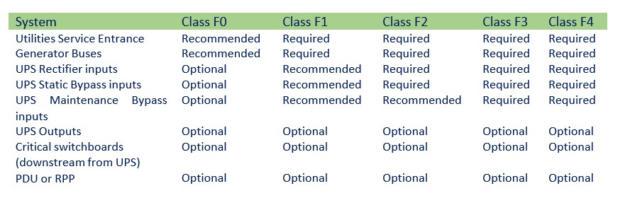
For lower Classes of data centers, SPDs are located at the utility entrance with transients not being addressed further downstream unless the site demands -for-it. For higher reliability Classes, SPDs are prevalent throughout the power system. As the data center Class increases, SPDs may be found in the following locations:
- Utility service entrances
- Generator buses
- UPS inputs
- UPS outputs
- UPS power distribution switchboards
- PDUs and critical power distribution panels
The installation of surge protective devices is a requirement for all data centers Class F1 and higher. A lack of surge protective devices would result in a Class F0 rating.
SPDs shall not be mounted inside the switchgear (unless specifically designed, manufactured, NRTL listed, and properly installed for integral installation) and shall be installed with minimum lead lengths and separation of Input/output wiring in order to perform properly.
No Comments