Power and Electrical Systems Design
- Introduction
- Transformers
- On Site Generation
- Availability
- Electrical Class Ratings
- UPS System
- Synchronization
- UPS Output Switchboards
- Ties and Interconnections
- UPS Output Distribution
- Power Distribution Units (PDUs)
- Direct Current (DC) Power Systems
- Computer Room Equipment Power Distribution
- Load Management
- Automation and Control, Monitoring
- Bonding, Grounding, Lightning Protection, and Surge Suppression
- Building Ground (Electrode) Ring
- Labeling and Signage
Introduction
Electrical distribution systems for data centers are designed to power the center safely and reliably and this section will also address the power distribution and monitoring solutions that have been successful in meeting these demands, and how data centers can be designed to create sustainable IT environments that can satisfy evolving business, financial and regulatory goals.
The electrical system design should not have a single point of failure as it may lead to interruption in the service and business continuity.
The site should be provided with enough electrical utility capacity to meet it is current and projected needs of the entire requirement of the datacenter.
The site should have multiple electrical source circuits with enough capacity to meet the entire site requirements.
The Datacenter should be in an area with easy sustainable circuit access to utility substations with a preference towards an area with utility circuits provided by two or more utility substations.
The site should have space for an electrical unit substation and its associated transformers and electrical utility circuit paths, and it should be located on the datacenter site in a secure way with accessibility.
Below Figure shows an overview of electrical transmission and distribution.
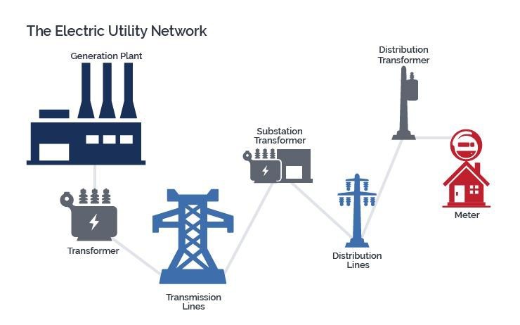
 AC Electricity Distribution from Generation Stations to Data Centers
Transformers
Transformers usually transform the utility’s medium distribution voltage to a lower voltage for utilization
by the data center.
The substation might transform voltage in excess of the site requirement and an on-site utility transformer might then transform the voltage to a lower voltage utilized by the building or facility.
The transformer size should be calculated based on the datacenter size, class and the load in the datacenter.
The Datacenter should have a dedicated transformers. The datacenter site should have considerable space for a minimum one electrical utility transformer and their associated electrical utility circuit paths and it must be located on the datacenter site in a secure and visible manner.
Datacenter is a critical infrastructure and it should have independent utility service to provide high availability services to the consumer.
Second power utility feed is advisable, but it depends on the uptime report of primary feed and benefits of a second power utility feed should be analyzed based on the mean time between failures (MTBF) to mean time to repair (MTTR) and power stability service to the data center.
A second power utility feed is recommended when the operational requirements of the data center results in an Operational Level 4, The availability requirements of the data center results in an Availability Ranking Level 4, The impact of downtime of the data center results in a Catastrophic classification, The reliability of the utility, based on the specific MTBF rates of the utility and the required mission time of the data center, is greater than 50%.
Electrical service entrance feed should have a minimum separation of 1.2 m (4 ft.) from other utilities along the entire route.
If redundant feeds are provided to the data center, it is recommended that the electrical service entrances to the facility have a minimum separation of 20 m (66 ft.) from the other electrical service entrances along the entire route.
At least two diversely routed electrical service feeds from different utility substations with each substation on separate power grids.
At least two diversely routed electrical service feeds from different utility substations with both
Substations on the same power grid.
At least two diversely routed electrical service feeds from one utility substation. One electrical service feed from one utility substation.
Utility services should be underground to the facility as it will reduce the potential threat to system failure caused by overhead utility line damage. Overhead utility service is not recommended as it poses a risk to the vehicle accident, wind and some other weather conditions.
On Site Generation
Backup generators should be there as a backup to data center equipment in case of utility power failure. Emergency generators should be there to power the data center life safety systems (e.g., emergency lighting, fire pumps) if utility power fails.
The datacenter site should have considerable space for one or more emergency and backup generators and their associated electrical utility and life safety circuit paths, and it should be located on the datacenter site in a secure manner.
The datacenter should have necessary fuel pumps, piping and on-site storage and the space required can dictate performance for a minimum 48 hours without outside services.
Availability
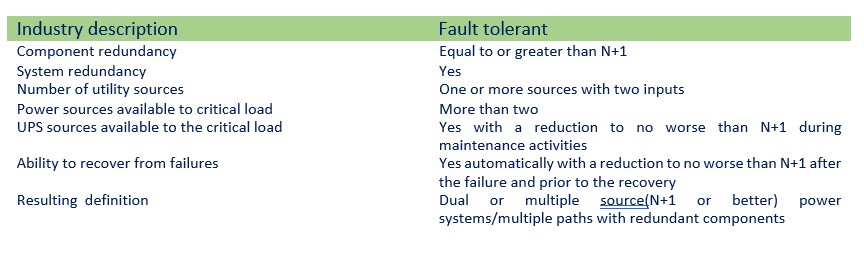
All electrical equipment must have redundancy to increase both fault tolerance and it must be documented well to maintain to avoid the outage due to human error, and this helps to maintain the overall redundancy in data centers.
The capacity is kW required to serve the load and plus the design margin and growth factors.
Capacity is the power required by the load and is designated as “N”. Higher levels of availability (based on
the criticality of the activity supported by the data center) require higher levels of redundancy. We recommend implementing below level of redundancy in Tier-3 and Tier 4 Datacenter.
2N Redundancy
2N redundancy provides two complete units, modules, paths, or systems for everyone required for a base system. 2N is also referred to as “dual-path topology.” Failure or maintenance of one entire unit, module, path, or system will not disrupt operations. For smaller fault-tolerant systems where a single module can accommodate the critical load, the 2N and N+ 1 model are synonymous.
(N+1) Redundancy
2(N+1) redundancy provides two complete (N+1) units, modules, paths, or systems. The failure or
Maintenance of one unit, module, path, or system will still leave intact a system with full redundancy and will not disrupt operations.
Multi-N Redundancy (xN)
A multi-N system topology is used primarily in fault tolerant or large-scale power systems where more than two large systems are employed together. In such a system topology, the critical load connection at the PDU or the branch circuiting level is the primary means of achieving the redundancy and Class of the system.
Below table displays four different levels of design efficiencies for an N+1 topology. For example, if N is
100 kVA, N+1 redundancy can be achieved in any one of the following ways:
- 2 × 100 kVA modules (50%)
- 3 × 50 kVA modules (66%)
- 4 × 33 kVA modules (75%)
- 5 × 25 kVA modules (80%)
Design Efficiency Ratios -Topology UPS or power systems ratio Design efficiency
(Required kW/installed kW)
- N 1:1 100%
- N+1 2:1 50%
- N+1 3:2 66%
- N+1 4:3 75%
- N+1 5:4 80%
- 2N 2:1 50%
- 2(N+1) 6:2 33%
- N + 2 3:1 33%
- N + 2 4:2 50%
- N + 2 5:3 60%
- N + 2 6:4 66%
Electrical Class Ratings
The standard includes five Classes relating to various levels of reliability of the data center facility infrastructure. The Classes are completely performance related, and it is mandatory to implement Class F3 and F4. The five Classes are:
- Class F0 - a single path data center that meets the minimum requirements of the standard, but doesn’t meet the requirements of an F1 or higher-level data center
- Class F1 - the single path data center
- Class F2 - the single path data center with redundant components
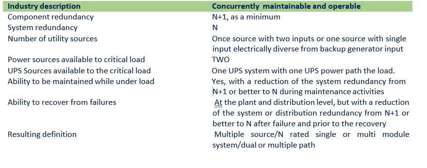
- Class F3 - the concurrently maintainable and operable data center
- Class F4 - the fault tolerant data center
Class F3
The Class F3 system possesses redundancy in the power paths to the critical load, but only one of those paths needs to be UPS powered.
The alternate path may be UPS powered, but this Class requires that it only be available and dedicated to the IT load.
On a dual-corded IT device, one input would be fed from the UPS power system, while the other input is fed from the non-UPS source.
The Class F3 system allows for complete maintenance during normal operations (on a planned basis), but it loses redundancy during maintenance and failure modes of operations. STSs are required for single- corded loads to provide power redundancy where no IT component redundancy exists. STSs are not required for dual-corded loads.
All maintenance and failure modes of operation are transparent to the load.
Class F4
A Class F4 system possesses redundancy in the power paths, and there may be more than two independent sources of UPS power to the critical load. The individual critical power systems are rated for the complete load for the 2(N+1)/system-plus-system option. For larger loads, the system may have multiple UPS systems where the system diversity is provided solely by the connection of the critical loads to the multiple UPS systems.
Each UPS system could be a multi-module UPS system or a single/high-kW UPS system. The fault tolerant system provides load source selection either via static transfer switches or by internal power supplies in the IT systems themselves.
There are no single points of failure in either the critical power system or the power systems supporting the mechanical or vital house/support loads. The Class F4 system allows for complete maintenance during normal operations and does not lose redundancy during either failure or maintenance modes of operations. All maintenance and failure modes of operation are transparent to the load.
UPS System
UPS and critical power system applications are focused on delivering quality power, whether originating from an electric utility or from internal energy storage, on an assured, 24/7 basis.
Datacenter should have reliable device to maintain the business continuity without any disruption. A UPS is usually required to provide stable power to sensitive active and passive equipment, and it can become single point of failure that affect multiple servers and business continuity disruption can be huge. So, resilience should be considered while planning the UPS for datacenter.
The primary concern of UPS system design for Class F3 and F4 systems is the maintenance of critical power services while accommodating known failures or allowing for safe and logical preventive maintenance.
Select a UPS that supports multiple power inputs, allowing two different sources to power the UPS unit. If one utility line fails, power from the other line can run the load and keep the UPS charged.
The Uptime Institute regards electricity from utility service providers as an unreliable source of power. Therefore, Tier 3 data center specifications require that the data center should have diesel generators as a backup for the utility power supply.
An automatic transfer switch (ATS) automatically should transfer the control to backup generator if the utility power supply goes down.
The Tier 3 data center specifications mandate two ATSs connected in parallel to ensure redundancy and concurrent maintainability.
Tier 3 data center specifications require the diesel generators to have a minimum of 12 hours of fuel supply as reserves. Redundancy can be achieved by having two tanks, each with 12 hours of fuel. In this case, concurrent maintainability can be ensured using two or more fuel pipes for the tanks. Fuel pipes can then be maintained without affecting flow of fuel to the generators.
Redundancy and concurrent availability can be achieved using separate power distribution panels for each ATS. This is because connecting two ATSs to a panel will necessitate bringing down both ATS units during panel maintenance or replacement.
The Tier 3 data center specifications require two or more power lines between each ATS and power distribution panel to ensure redundancy and concurrent maintainability.
Each power distribution panel and UPS should also have two or more lines for the same purpose.
Power from the distribution panel is used by the UPS and supplied to the power distribution boxes for server racks as well as a network infrastructure. For example, if a 20 KVA UPS is required for a data center, redundancy can be achieved by deploying two 20 KVA UPS or four 7 KVA UPS units. Redundancy can even be achieved with five 5 KVA UPS units.
The Tier 3 data center specifications require that each UPS be connected to just a single distribution box for redundancy and concurrent maintainability. This ensures that only a single power distribution circuit goes down, in case of a UPS failure or maintenance.
Each server rack must have two power distribution boxes in order to conform to Tier 3 data center specifications. The servers in each rack should have dual power supply features so that they can connect to the power distribution boxes.
A static switch can be used for devices which lack dual power mode features. This switch takes in supply from both power distribution boxes and gives a single output.
The static switch can transfer from a power distribution box to another in case of failures, within a few milliseconds.
A data center built according to Tier 3 data center specifications should satisfy two key requirements: redundancy and concurrent maintainability. It requires at least n+1 redundancy as well as concurrent maintainability for all power and cooling components and distribution systems.
A component’s lack of availability due to failure (or maintenance) should not affect the infrastructure’s
normal functioning.
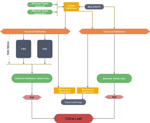
Class F3 Model provides multiple power paths as close to the critical load as possible and Class F4 Model include different number of UPS power plants versus the number of UPS Power delivery path.
The static bypass, the maintenance bypass, the output breaker, and any load bank testing connections can all have a direct impact on the maintenance and failure response of the UPS system.
Bypass configurations can affect UPS functionality as follows:
- Combining maintenance bypass and static bypass paths from a single input feeder will typically result in a lower Class because it reduces the ability to remove a module or system without interrupting the service to the downstream critical loads.
- Load bank connections that are independent of the UPS output source can contribute to a high Class because they allow for testing without interrupting the service to the downstream critical loads.
- Locating circuit breakers on the collector bus or on the output bus of paralleled UPS systems rather than Making them internal to a power module will contribute to a high Class by allowing a module to be removed from the service without shutting down the entire system. These are also known as isolation breakers.
- The presence of a maintenance bypass will allow for the removal or testing of a UPS module or for the replacement of a static switch in the event of a catastrophic failure. This has a dramatic effect on the mean time to repair (MTTR).
Maintenance bypass is mandatory for all Class F3 and F4 applications and for system control cabinets.
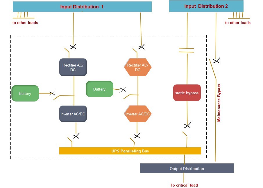
When the input to the rectifier and the static bypass originate from one bus (Input Distribution 1) and the maintenance bypass originates from a separate bus (Input Distribution 2), the critical load shall be transferred without interruption or disturbance to an isolated source, either utility or generator, depending on the design, while the UPS is repaired or tested.
When other loads are connected to the bus that support either the rectifier and static bypass (Input Distribution 1) or the maintenance bypass (Input Distribution 2), the designer shall also consider how any disturbance on the input bus could affect the critical load while operating in this mode and (how to minimize the disturbance). This type of design, including disturbances may be caused by:
- Testing of the UPS
- Testing of other loads connected to the same bus
- Turning on and off other loads connected to the same bus
- Fault conditions
Inputs to the static bypass and maintenance bypass shall not be derived from separate sources unless the two sources are synchronized in phase and frequency. Lack of synchronization will result in an unreliable design that should require open transition (i.e., shut down the loads and then restart from the alternate source.
Note that synchronization of sources is difficult because load imbalances and phase shifts (such as transformers introduced downstream) can force circuits out of synchronization. The best practice is to power both the static bypass and the maintenance bypasses from the same source.
The UPS system static bypass and maintenance bypass designs should consider using the same source or type of source for the closed transition transfer mechanisms.
This would require the power module inputs, static bypass input, and the maintenance bypass input to be synchronized to the same source.
Depending upon the configuration, some UPS could be exempted from this rule when the static bypass input and the output of the UPS are synchronized. For example, input to power module inputs could be fed from utility 480 VAC wye source “A” while the static bypass and maintenance bypass could be fed from utility (or generator) 480 VAC wye source “B”.
Other UPS configurations may have the maintenance bypass external to the UPS system to enable the UPS to be taken off-line for maintenance or replacement. It is acceptable to have the maintenance bypass internal to the UPS system in a Catcher system since the Standby UPS system can function as the external alternate path in the event the UPS system needs to be taken off-line for maintenance or replacement.
Attention shall be paid with respect to the configuration of disconnects external and internal to the UPS
system to enable maintenance of rectifiers, inverters, or static bypass components in a safe manner.
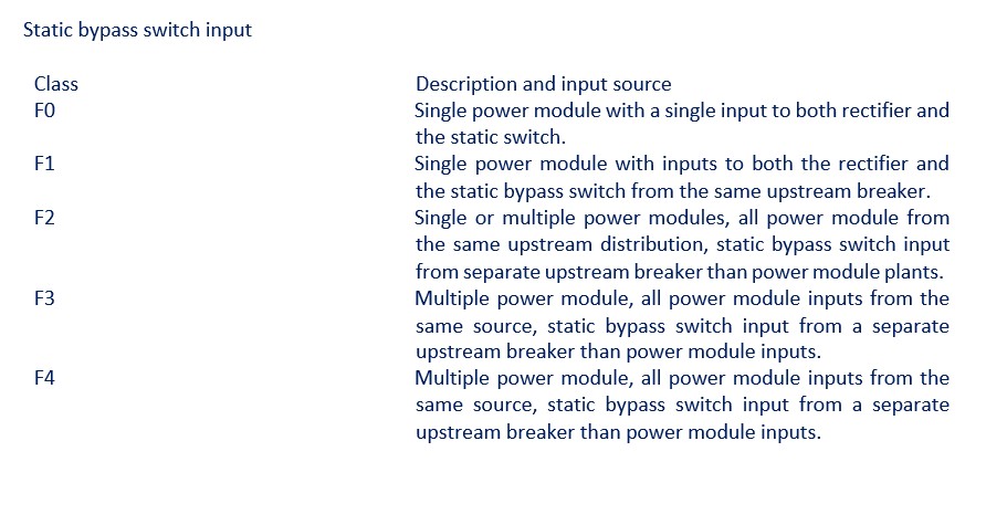
A dedicated input to the static switch that is separate from the rectifier input allows the critical load to further sustain faults that could be associated with the rectifier. In Class F0 and Class F1 applications, a single source of input power for both the rectifier and the static bypass is permitted.
Synchronization
Synchronization can occur in one of two ways for UPS systems:
- Actively based on some form of external control system
- Passively by the management of the static switch inputs to the given modules or via active systems specific to the UPS manufacturer, depending upon the chosen UPS topology.
The active systems offer excellent synchronization functionality, especially when the UPS system uses batteries.
The passive system is important as vital system transfers are assured to be coordinated when the static inputs are managed and considered in the design. A lack of input or output synchronization could result in a failure of ASTS operation or an out-of-phase transfer, thereby resulting in a dropped load and possible equipment damage.
UPS systems shall be synchronized in one of two ways:
- Line-side (source) synchronization
- Load-side (output) synchronization
In either event, synchronization is vital and shall be required for a high-reliability system at the Class F3 and Class F4 levels. Since Class F0, Class F1, and sometimes Class F2 systems are single module/single plant systems, no external synchronization is required.
When system-level synchronization is not possible, static switching at the loads or critical power buses may be required.
UPS Output Switchboards
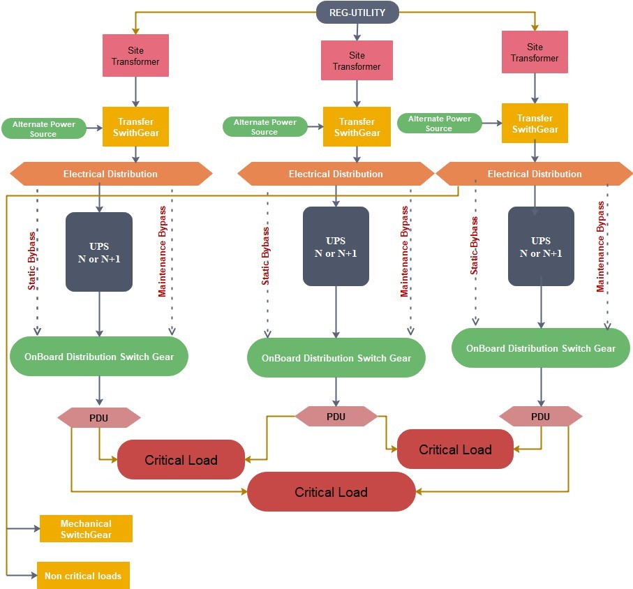
Output switchboards directly support the PDU and ASTS systems downstream of the UPS power plants. For Class F1, F2, and F3 systems, UPS outputs should be vertically organized to the UPS output distribution system downstream. Simpler electrical topologies may not have separate UPS output switchboards and critical power distribution switchboards.
For Class F3 systems, the second path may be derived from a non-UPS source. For Class F4 systems, there may be multiple power paths, but these are kept separated until they meet at the critical load.
Ties and Interconnections
If the UPS sources are synchronized and are not overloaded, UPS systems may transfer load between each other. Except on a plant level, the UPS is the foundation of the multi corded system for critical loads.
All transfers are done via closed-transition, and the control systems for this type of operation are typically redundant or offer some other form of manual operation if the control system fails.
System ties are common in system-plus-system configurations, and several UPS system manufacturers offer pre-engineered solutions for this design feature. For xN or other types of UPS topologies, the system designer shall engineer a solution for the given UPS module and plant configuration.
Ties and interconnections should also prevent the propagation of failures and should limit short circuit fault current.
UPS Output Distribution
UPS output distribution switchboards are located immediately downstream of the UPS power plants and extend to the PDU or data processing room levels.
One important consideration for these systems is that they do not have to follow the redundancy level or plant counts found in the UPS power plants.
Class F1 systems, the UPS output distribution switchboards are single units.
Class F2 systems, there may be module redundancy, but there may not be UPS power path redundancy. In both cases, UPS systems would match the total UPS power paths.
In a Class F3 system with a single UPS power plant, there are at least two UPS output powered critical distribution switchboards, one on the active path and one on the alternate, or non-UPS, path.
For a Class F4 system, there are at least two critical power switchboards, if not more.
UPS output distribution switchboards may come in numerous specifications and configurations, all depending on the maintenance and failure mode of the critical loads downstream and UPS systems upstream.
Power Distribution Units (PDUs)
PDUs with an isolation transformer create a separately derived neutral for downstream loads although this may not be necessary for 3-phase loads or for systems in which the load utilization voltage is created at the UPS.
PDUs with transformers convert the output voltage of the UPS system to the utilization voltage of the critical loads as needed.
The PDU should have output branch circuit panel boards or distribution circuit breakers that serve the downstream critical loads or subpanel boards serving downstream critical loads.
If the PDU has an isolation transformer, its inrush characteristics should be coordinated with the upstream UPS peak load tolerances for normal, failure, and maintenance modes of operation. Low inrush transformers may also be employed depending on the UPS system’s design.
Where PDUs are expected to run close to their rated loads or one or more loads will generate large harmonic currents, a K-factor transformer might be considered.
Harmonic currents can be created by the ITE (e.g., switched mode power supplies [SMPS]), but they can also be created by fans or drives that are connected to the PDU critical bus.
High harmonic currents, especially those caused by single-phase power supplies in the ITE that create triplen harmonics (odd multiples of the 3rd harmonic, such as 3rd, 9th, 15th, 21st), can cause PDU output voltage distortion and transformer overheating. This heating reduces the efficiency of the transformer and increases the load on cooling equipment. These problems can be exacerbated when the PDU’s transformer is operated close to its rated capacity.
Transformers are frequently rated to K-9, but they may also be as high as K-13 to K-20. K-factor rated transformers are larger, more expensive, and less efficient than non-K-rated transformers, thereby increasing both capital and operating expenses, so they should be deployed judiciously.
For Class F3 and Class F4 facilities where the transformer seldom operates at greater than 40% of its rated load, K-factor rated transformers may not be necessary as harmonics can be tolerated up to a certain level.
- It may have a harmonic-tolerant (or K-rated) transformer.
- It may have a low inrush transformer to prevent unintended upstream circuit breaker trip.
Direct Current (DC) Power Systems
DC power systems that serve critical loads are common in two forms:
- The primary power source for access provider and carrier equipment.
- As an alternative to AC power in computer rooms because of energy efficiency, design simplification and ease of paralleling alternative energy sources DC power distribution systems function within the data center in the same way as the AC systems providing power to a variety of loads. However, DC-based systems can offer additional features that can be attractive to data center designers and operators. It is also possible to mix DC and AC systems in hybrid configurations, for example, providing DC to critical loads and AC to mechanical loads.
DC power system operating voltages are affected by several factors such as:
- Battery technology (e.g., lead-acid varieties, nickel-cadmium, nickel-metal-hydride, lithium-ion varieties, sodium varieties, flow varieties)
- Rectifier output regulation in maintaining constant voltage under dynamic loads
- Voltage drops in DC power conductors—cable sizes and lengths
- Operating voltage limits of various connected loads
- Derating for environmental conditions such as altitude
- All DC equipment shall be properly and clearly marked according to the applicable electrical or building codes and as required by the appropriate listing agency. DC equipment includes, but is not limited to:
- Cords
- Cables
- Raceways
- Bus ways
- Power connectors
- Junction boxes
- Batteries
- Generators
- Flywheels
- Circuit breakers
- PDUs
- Rectifiers
- DC-UPS
The design of all DC-powered ITE shall likewise comply with applicable sections of required electrical and building codes and shall be rated, listed, and marked for DC operation at the anticipated voltage range.
Electrical safety clearance rules are applicable to both AC and DC circuits. For DC circuits, the clearance requirements shall generally be the same as those for AC circuits having the same nominal voltage to ground.
Direct current systems should meet the same requirements for availability, reliability, maintenance, and safety as AC power systems.
DC-based critical power systems are an emerging and potentially viable option for mission-critical environments, it is advisable at the present time to work closely with the designers, equipment providers, and electrical contractors who have experience in the direct current applications.
Designers, operators and others involved in DC systems should refer to the appropriate standards such as:
- Over current protection devices (OCPD) and disconnect devices for DC power systems will need further investigation for higher voltage DC systems. AC-rated devices cannot automatically be used on a DC power system at the same rated voltage and current.
- The established 2:1 protection coordination scheme for DC fuses is not readily applicable since data centers typically utilize circuit breaker technology.
- Transients for other than 48 VDC systems are not well described.
- Battery disconnect or other DC disconnect usage at voltages above 50 VDC is not well established.
- Disconnects may not be required, depending upon local requirements. 2-pole or even 3-pole disconnects may be required, perhaps at multiple points within a system. Interrupting capacity and withstand ratings may need to be selectively coordinated.
- Conductor sizing regulations for DC are not well established; sizing per AC code requirements may
be inappropriate for DC conductors. - If the rectifier technology is switched mode power supply (SMPS), it may require use of electrical noise control via power line filters (possibly connected to the return or DC equipment ground conductor) and might create additional audible noise from cooling fans.
- Rectifier operation modes at the higher voltages, such as 380 VDC, may need verification for AC
input power factor correction, load sharing, paralleling, voltage sensing, and current limitation. - The DC power distribution topology is historically bus or cabling. Further, there may also be a need for an underfloor topology. Distribution (such as rigid bus bar) withstand under extreme fault current conditions (such as a direct short across the batteries [if batteries are used]) will probably vary considerably from that for telecommunications 48 VDC system.
- Voltage drop is a concern, especially if DC is run for distances longer than a few meters. Guidelines for calculating voltage drop can be found in IEEE 946.
- For metallic battery racks, determine the local authority requirements for sizing the bonding conductor. 13.3 mm2 (6 AWG), which is typically specified for telecommunications applications below 50 VDC, may not be acceptable for higher voltages (e.g., 380 VDC).
- Consult with the local authority regarding limitations for the location of centralized DC power systems in the computer room.
- Determine the grounding methods required by the ITE. The 380 VDC system might be operated
as a positive grounded system (similar to the 48 VDC telecommunications system) as a negative grounded system (similar to the 24 VDC telecommunications system) or as an ungrounded system (similar to higher voltage UPS systems).
Computer Room Equipment Power Distribution
The distribution to the critical loads must be exactly mapped to the redundancy of those loads and the cord and circuit diversity that they require.
The upstream systems must be able to deliver the source diversity to the computer room circuiting under normal maintenance and failure modes of operation as prescribed in the Class performance descriptions.
At this level, the electrical system is downstream from the PDU or transformer level, and this system is typically operating at the utilization voltage level for the ITE or critical equipment. This distribution can be present in several forms such as bus way or individual circuits.
For high-density loads, a given design may separate the panel board branch circuit sections of the PDU into cabinets near the critical loads. This system may have either single or dual-inputs and is commonly known as a remote power panel (RPP). RPPs reduce installation labor and reduce the cable and circuit length to the load.
Distribution to the loads may be either overhead or underfloor. Underfloor power distribution is most commonly accomplished using liquid tight flexible metallic conduit, although in some jurisdictions, hard conduit may be required. IEEE 1100 recommends hard steel conduit with the Rwanda standards board approved insulated grounding wire for added safety, performance, and protection.
Power distribution should be located under the cold aisle and telecommunications cabling located under the hot aisle to minimize air blockages.
Overhead power distribution can frequently eliminate the cost of conduits (with the addition of cable tray or bus way) and can have the added benefit of eliminating cables as a cause of underfloor air blockage.
Overhead cabling, if used, should be planned to minimize blockage of airflow above the floor.
For future and high-density loads, traditional 20A circuits may not be enough for power strips in the IT cabinets, and in some installations, 3-phase power strips with appropriately sized circuit capacity may be required to support the load. To accommodate future power requirements, installation of three-phase cabling at a capacity of up to 50 or 60 A or at utilization voltages of around 400 VAC is recommended even if such power is not immediately required.
Load Management
Unused or abandoned cables not terminated at equipment or marked for future use shall be removed. Load connection best practices for facilities are listed below:
- Twist-lock receptacles and plugs for all underfloor or overhead receptacles should be provided.
- Receptacles on the power strip within a cabinet or rack do not require locking-type receptacles.
- Some systems use a plug-in bus way system installed adjacent to the loads or cabinets. The bus way’s design should allow new load taps to be installed while the bus is energized without creating any arcing or transients.
Locking receptacles should be used for connecting the input cords of the power strips and for larger ITE. For in-rack loads using straight-blade cords, anti-pullout tie downs should be used where cords plug into the power strips.
Power distribution cables originating from different source PDUs, RPPs, electrical phases, taps off the same PDU, or electrical panels should be clearly identified as to their source, phase, and load capacity.
If permitted or required by the Rwanda Standards Board, cables from different sources may have different color jackets and connectors.
Branch circuit overload protection devices should be de-rated by a design factor of 20% (e.g., be at least
25% larger than their connected ITE load) to ensure that circuits are not operating at the edge of their
circuit breaker trip rating.
- For equipment and systems that require power feeds from more than one power source to provide availability (typically Class F3 or Class F4), the power cords should be split across two of the cabinet power strips. To provide availability for single-corded equipment and for equipment that utilizes multiple cords but is not power feed-fault tolerant, these items should be plugged into a rack-mounted power strip or receptacle fed by a larger upstream, automatic static transfer switch (ASTS), or some other point-of use ASTS.
- Equipment with three power cords should have one of the three plugs on a rack-mounted power strip or receptacle fed by a static transfer switch or point-of-use switch. The other two plugs should be plugged into receptacles supported by different PDUs. These other two receptacles should not be on static transfer switches.
- Power cords should be mechanically connected at the point of entry to the rack or a piece of ITE. This may be accomplished via the ITE manufacturer’s cable tie downs, hook-and-eye straps, cable ties, or similar attachment that allow for the secure attachment of the power cable to the enclosure and would prevent the accidental disconnection or damage of cable. Provide slack loop, as appropriate, in the tie down to allow for some cable movement.
-
UPS sources should be paired or grouped together and represented by individual panels or remote power panels for ease and clarity.
-
Plugs and rack-mounted power strips should be located where thermos graphic testing can observe all critical connections and over-current protection devices while operating.
-
Cable management should be used.
-
Disruption to future operations should be minimized by locating distribution equipment to permit expansion and servicing with minimal disruption.
-
All power receptacles and junction boxes should be labeled with the PDU/RPP/panel number and circuit breaker number. Each PDU/RPP/panel circuit breaker should be labeled with the name of the cabinet or rack, or the grid coordinates of the equipment that it supports.
-
All power receptacles and junction boxes installed under an access floor system should be attached to the access floor or the structural floor per manufacturer’s recommendations when required by the Rwanda Standards Board.
-
Receptacles and junction boxes should be mounted on a channel to keep raceways and equipment above the subfloor. This attachment may be made mechanically via concrete anchors, brackets attached to the access floor pedestals, or even industrial hook-and-loop NRTL-listed fasteners, which make an excellent, dust-free alternative to drilling in an anchor or adhesives. Additionally, boxes and other electrical devices should be mounted at least 25 mm (1 in) above the subfloor to prevent water intrusion in the event of a leak.
-
Every computer room, entrance room, access provider room, and service provider room circuit should be labeled at the receptacle with the PDU or panel board identifier and circuit breaker number.
-
Receptacles on UPS power should be color coded, have a color-coded label, or have a colored dot to indicate the specific upstream UPS power source.
-
Supply circuits and interconnecting cables identified for future use should be marked with a tag of enough durability to withstand the environment involved.
Automation and Control, Monitoring
Monitoring is defined as the telemetry and ability to view what is going on within a given system. In some cases, monitoring systems can integrate and manage alarm and trouble signals from the monitored systems.
For the purposes of this section, control is defined as any device that directly regulates a change in state in a given system. Controls are an active system, and may be either:
- Manually initiated and automatically operated based on human input or decision
- Automatically initiated and operated based on a predetermined script or response to a failure or external change of state.
Operators should be able to respond to failures or to determine the loading or operation of their systems.
Monitoring is mandatory for all Classes with increasing levels of observation scope and granularity with increasing Class.
As Class level increases, monitoring increases by replacing summary alarms with individual alarm points and by presenting systems virtually for the system operators.
For Class F4 systems, a virtual single line, which clearly shows system loading and power flow, should be provided. In some instances, a simulator is also provided where changes of state can be tried in a virtual setting to see the outcome prior to employing them in the live, working environment.
Electrical systems should disclose all changes in state, alarms, pre-alarms and positions of all breakers, and switches as well as general system information.
Power quality monitoring (PQM) for data centers is recommended since IT systems may be sensitive to power quality, transients, harmonics, and other types of waveform disruption.
Power monitoring is also vital as waveform disturbances offer a precise definition of experienced failures and outages. When addressing power system monitoring, there are three facets of observation:
- Power levels noting voltage, current, and frequency
- Harmonic content
- Waveform imaging and capture
Power monitoring offers a sampling of the power system’s quality in a manner like a mechanical system’s
monitoring of temperature or water chemistry to the chiller/cooling system.
PQM should be located at portions of the electrical system that offer a complete view of the vital locations where power is being converted.
No favor is made over switchgear-integrated monitoring or stand-alone systems. The key element is how they are used.
Bonding, Grounding, Lightning Protection, and Surge Suppression
The comprehensive electrical protection required for the critical facility is achieved using a system approach to integrate lightning protection, overvoltage and surge suppression, bonding and grounding.
Grounding is addressed in three sections: electrical distribution, PDU, and within the computer room. Electrical system grounding is consistently misunderstood and, for most facilities, not adequately maintained, changed or integrated to the ITE loads that it serves.
It is the intent of this standard to provide a bonding and grounding system that substantially equalizes any no transient potential differences so that all the enclosures, raceways, and all bonded metal found in the computer room are effectively at the same ground potential (substantially equalized).
Bonding and grounding of data centers relates most specifically to maintaining the facility’s common electrical bonding and grounding system along with any desired supplementary bonding and grounding for the ITE.
Bonding and grounding also address vital issues such as harmonic current management and fault current mitigation.
Bonding and grounding also integrate voltage transient suppression by the application of SPD (surge protection device) systems as well as lightning protection systems.
The bonding and grounding system are one of the few electrical systems completely systemic to the entire critical facility.
If properly organized and installed, the ground system is essentially a radial system from the electrical service entrance. There are a few subtleties for critical facilities that vary from other buildings.
Where generators are not treated as separately derived sources, neutrals and grounds are routed with the associated phase wiring and carried back (without being switched) to the main service and terminated on the main service’s neutral and ground buses.
Where generators are treated as separately derived sources, grounds are carried back to the main service and terminated on the main services ground bus.
Data center bonding and grounding addresses all bonding and grounding work within the critical environment.
These systems include:
- The separately derived system at the PDU
- Ground path to the load
- Critical environment grounding—supplementary at the ITE
- ITE bonding and grounding
- Personal grounding and static discharge.
Bonding and grounding for a data center involve several entities such as:
- A common grounding electrode system (GES) for the building, involving the intersystem bonding of a:
– Grounding electrode system for the electrical power
– Grounding electrode system for the lightning protection system (LPS)
– Grounding electrode system for the telecommunications service provider cables and protectors - Grounding electrode conductors for solidly grounding each power service entrance
- Grounding electrode conductors for solidly grounding each separately derived power source such as an engine-generator for standby power
- Grounding electrode conductors for solidly grounding each telecommunications service entrance
Bonding and grounding infrastructure for telecommunications utilizing components such as the BCT, TMGB, TBB, TGB, and GE as described in TIA-607-B
- Equipment grounding conductor for power distribution from the service/source to the load
- Structural metal
- Grounding conductors such as the down conductors for an LPS and SPDs
- The common bonding network (CBN) within the building
- Supplemental bonding and grounding structures for electronic equipment such as:
– Mesh-bonding network (mesh-BN)
– Isolated bonding network (IBN)
– Supplementary bonding grid.
The common bonding network (CBN) is the set of metallic components that are intentionally or incidentally interconnected to form the bonding network (a mesh) in a building. The CBN always has a mesh topology and connects to the grounding electrode system via one or more grounding conductors.
Serving power systems and electronic equipment bonding and grounding primarily involves the serving power source and the power distribution to the IT and other electronic equipment.
This primary level of bonding and grounding is required to be in accordance with the NRTL product safety listing of the power system and the electronic equipment (load).
The entities of concern are the grounding electrode conductor (system) and equipment grounding
(bonding) conductor (or green wire).
These dedicated circuit conductors are required for the safe operation of the equipment, including any ground faults.
In some instances, equipment may be designed as “double insulated,” whereby the NRTL requirements for the equipment grounding conductor may be eliminated (e.g., a two-prong plug or receptacle). Although data center electrical and electronic equipment may be considered “grounded” according to its NRTL requirements, supplementary bonding and grounding are recommended.
High-resistance/impedance grounding (HRG) systems can be used in lieu of solidly grounded systems. HRGs are typically designed to limit a ground fault current to 10 Amps or less. The advantages of using HRGs are:
- Safety enhancements because of mitigation of phase-to-ground fault currents
- Operational enhancements because of reduction of ground fault current trips
- Reduced cost because of the elimination of four-wire feeders
The HRGS (High Resistance Grounding System) are installed at the service transformer. They function down to the first separately derived source in the distribution system. Where used for ITE installations, consideration should be given to any impact on the resistance/impedance of the grounding systems.
HRGs (High Resistance Grounding System) may influence the level of electrical noise versus earth ground at higher frequencies such as for filters. The impact may occur because of reactance of the resistance/impedance devices such as an inductor or wire-wound resistor. Inductive/reactance grounded power systems are not recommended for low-voltage systems.
Check with the UPS system manufacturer if it is not connected to solidly ground neutral sources as they
typically will provide “neutral” grounding kits for their UPSs.
The following considerations are important for understanding the complexities of bonding and grounding for a data center:
- All dead metal objects within the data center should be grounded (this includes empty cabinets and racks and ladder racks).
- Equipotential grounding becomes increasingly difficult across an expanse such as a building or larger data center.
- Distributed grounding (within a building or complex) cannot accomplish equipotential grounding.
- A dedicated and separate ground for data center equipment is NOT recommended and is entirely likely to be an electrical safety violation.
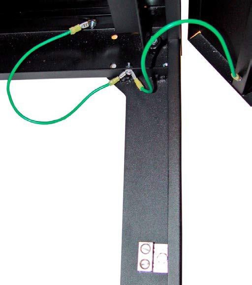
- Especially where multiple services (power and communications) enter the building at separated locations, a buried ground ring is recommended to provide equipotential bonding. Where multiple power service entrances are involved, the ground ring conductor should be sized at 107 mm2 (4/0 AWG) minimum bare copper.
- Where equipment is designed for double insulation, grounding that equipment may be a secondary concern (pending its product safety listing requirements and electromagnetic emissions compliance).
- Any electrical grounding infrastructure placed for the electrical power system should not replace the separate bonding and grounding infrastructure for telecommunications (TIA-607- B).
- The infrastructure described in TIA-607-B is better placed in the central portions of the building and away from exterior locations where lightning current activity is more likely.
- Supplementary bonding and grounding of data center equipment is recommended (this is over and above bonding and grounding of the serving power distribution) as it:
- Provides for more locally grounded equipment
- Maintains a level of grounding even if the serving power circuit grounding is interrupted
- Provides dispersed path(s) for ESD currents to follow
- Provides conductive paths among interconnected equipment where common configurations include grids and planes.
- Further reduce the levels of inter-unit common-mode electrical noise on signal and power cabling, Provide a lower resistance and lower impedance inter-unit ground reference
- Reduce damage to inter-unit equipment during power fault and surge events
- An isolated bonding network (IBN) may be utilized for certain telecommunications applications
- The electronic equipment system is only grounded via a single point connection window.
- This concept has been used by the telecommunications service providers (primarily for DC powered systems but may also be applicable for AC powered systems).
- Data circuits between data centers and different floors should be decoupled to prevent issues related to unwanted electrical transients. Fiber optic circuits and links are ideal for decoupling. Some types of circuits may utilize suitable transformer isolation for decoupling.
Lightning Protection
Lightning events can cause fires, damage to buildings, and breakdowns of electrical, telephone, and computer installations, which may result in considerable losses in operational revenues and increased customer dissatisfaction.
Damage results from electromagnetic fields from the lightning strike, voltage differentials in ground systems, and structural damage from ohmic heating or mechanical forces. This damage can be attributed to insufficient direct strike protection;
Deficient grounding; bonding and shielding techniques for the susceptibility level of the installed electronic equipment systems; and deficient selection and installation of surge protective devices.
Depending on the geographical location for the data center, there may be local guides available specific to the country or region, such as the risk analysis guide provided in fire protection by Rwanda standard board , which takes into account geographical location and building construction among other factors in determining the suitability of a lightning protection system.
If a lightning protection system is installed, it shall be bonded to the building grounding system as required by the prevailing standards and the local authority and as required for maximum equipment protection.
For some locations, lightning protection is required by local authority for basic building safety and protection.
If a lightning protection system is present, the lightning protection system shall be:
- Applied as a comprehensive system
- Integrated with properly sized and installed SPDs(Surge Protection Device)
- Implemented to cover all systems and buildings serving the critical environment.
Where protection from lightning-caused voltage fluctuations and transients is to be provided for protection of critical facilities, installation should be in accordance with industry recognized standards as per the local regulations authority.
Surge Suppression/Surge Protective Devices (SPDs)
Surge suppression, as used in this section, encompasses all surge protective devices or SPDs.
Within surge suppression for low voltage AC power circuits, the term surge protective device (SPD) has replaced the term transient voltage surge suppression (TVSS) with TVSS no longer in use.
Surges and transient power anomalies are potentially destructive electrical disturbances with the most damaging being overvoltage occurrences and short duration events.
High-energy transient power anomalies can arise from inductive load switching or other events within the power system or from capacitive and inductive coupling from environmental events such as nearby lightning activity.
Environmental and inductive power anomalies are wideband occurrences with a frequency range from close to DC to well into the RF high-frequency spectrum. It is critical that each point-of-entry (e.g., power, HVAC, telephone, LAN, signal/control, RF) into the equipment area be protected against these anomalies.
This protection is essential to reduce the risk of personal injury, physical equipment damage, and loss of operations. Although lightning can cause the most visible damage, it is not the predominant cause of transient voltages.
Sources of transient voltage include, but are not limited to:
- Power Company switching
- Generator transfer
- Shared commercial feeders with poor line regulation
- Load switching
- Fault currents
- HVAC units
- Heating elements
- Power tools
- Electric motors
- Fluorescent lights.
SPDs and large-scale surge suppression are an integral part of the high voltage lightning protection for a facility.
Additional low voltage transient mitigation is typical for an information technology facility to protect against internally generated transient events.
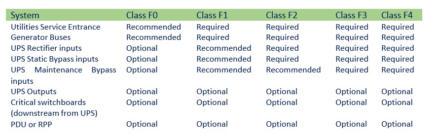
For lower Classes of data centers, SPDs are located at the utility entrance with transients not being addressed further downstream unless the site demands -for-it. For higher reliability Classes, SPDs are prevalent throughout the power system. As the data center Class increases, SPDs may be found in the following locations:
- Utility service entrances
- Generator buses
- UPS inputs
- UPS outputs
- UPS power distribution switchboards
- PDUs and critical power distribution panels
The installation of surge protective devices is a requirement for all data centers Class F1 and higher. A lack of surge protective devices would result in a Class F0 rating.
SPDs shall not be mounted inside the switchgear (unless specifically designed, manufactured, NRTL listed, and properly installed for integral installation) and shall be installed with minimum lead lengths and separation of Input/output wiring in order to perform properly.
Building Ground (Electrode) Ring
A building ground electrode ring shall be installed for facilities where a lightning protection system is installed or where there are multiple power service entrance locations along the periphery of the facility.
As required by local codes and standards, the ground ring shall be bonded to structural metal at every other column or more often. Concrete-encased electrodes (also known as Ufer electrodes) shall be used in new construction as a method of supplementing the grounding electrode system.
Concrete-encased electrodes improve the effectiveness of the grounding electrode system because of concrete having hygroscopic properties and by providing a much larger surface area in direct contact with the surrounding soil:
- Concrete-encased electrodes shall be encased by at least 51 mm (2 in) of concrete, located within and near the bottom of a concrete foundation or footing that is in direct contact with the earth.
- Concrete-encased electrodes shall be at least 6 m (19.7 ft) of bare copper conductor not smaller than 21.1 mm2 (4 AWG) or at least 6 m (19.7 ft) of one or more bare or zinc galvanized or other conductive coated steel reinforcing bars or rods at least 12.7 mm (0.5 in) in diameter.
- Concrete-encased electrodes shall be bonded to any other grounding electrode system at the site.
- This building grounding system shall be directly bonded to all major power distribution equipment, including all switchgear, generators, UPS systems, and transformers, as well as to the telecommunications systems and lightning protection system. The facility shall possess a building electrical main ground bus (MGB) where all the large-load feeder facility grounds terminate. This is the location, coupled with the telecommunications main grounding bus bar (TMGB), where the grounding system can be validated for both continuity and impedance.
A building ground electrode ring should be installed for all facilities.
Single or triplex ground rod fields as the only earthling vehicle are not adequate for a critical facility.
The direct burial connections should meet appropriate electrical testing requirements as set out in the applicable standards and codes to ensure durability.
Designs may vary according to the site parameters such as available real estate, earth resistivity, frost line level, and the depth of the water table.
Ground bus bars should be placed to facilitate bonding and visual inspection.
The ground ring should be 107 mm2 (4/0 AWG) minimum bare copper wire buried a minimum 800 mm (30 in) deep and a minimum 1 m (3 ft.) from the building wall. For larger sizes, stranded conductors are recommended.
Ground rings encircling buildings should be installed just beyond the roof drip line.
The size of the ground ring conductor is recommended to be the same as the largest size required by the Rwanda Standards Board for a grounding electrode conductor to promote the accomplishment of intersystem bonding.
The ground rods should be connected to the ground ring. Typical ground rods are 19 mm by 3 m (3/4 in by 10 ft) copper-clad steel ground rods spaced every 6 to 12 m (20 to 40 ft) along the perimeter ground loop.
Test wells for the building ground electrode ring should be provided at the four corners of the loop.
The common grounding electrode system should not exceed 5 ohms to true earth ground as measured by the fall of potential method (IEEE 81). As noted in the NEC, IEEE 1100, and IEEE142, common bonding of different systems plays a crucial role along with grounding.
Supplementary bonding and grounding methods are those provided in addition to the bonding and grounding measures typically required by the applicable electrical safety codes and product safety standards.
Supplementary bonding and grounding methods are intended to improve facility and equipment performance related to bonding and grounding. Examples of supplementary bonding and grounding entities may include metallic raceways, racks and cable trays; under the raised floor or above the cabinet and rack metallic grid work; metal plates and metal sheets; multiple bonding conductors from equipment to a grounding/bonding structure, etc.
An integral part of the bonding and grounding network in the access floor area or any critical environment is the grounding of the IT support equipment and static discharge management during ongoing operations. This includes the connection of a cabinet of ITE chassis to the mesh-BN, connections between various IT systems and cabinets, and personal grounding checks and static charge dissipation.
Rack Connections to the Mesh-BN It is common for cabinets to be physically connected for structural integrity, and they also may be logically, virtually, or network connected, acting as an integral platform.
This is achieved by the manufacturer assembling the cabinet or rack in such a way that there is electrical continuity throughout its structural members. For welded racks, the welded construction serves as the method of bonding the structural members of the rack together.
All adjacent cabinets and systems should be bonded in order to form grounding continuity throughout the rack structure itself.
Electrical continuity cannot be assumed using a nut and bolt connections used to build or stabilize equipment cabinets and racks.
Bolts, nuts, and screws used for rack assembly may not be specifically designed for grounding purposes, and unless grounding bonding jumpers are installed, do not assume electrical continuity for the cabinet lineup.
Most cabinets and racks are painted, and as paint is nonconductive, this negates any attempt to accomplish desired grounding. Therefore, paint or cabinet coating must be removed in the bonding area for a proper bond to be formed.
Most power is routed over the top or bottom of the rack. Without a reliable bond of all four sides of the rack, a safety hazard exists from potential contact with live feeds.
Personal Grounding and Static Discharge
Electrostatic discharge (ESD) is the spontaneous transfer of electrostatic charge. The charge flows through a spark (static discharge) between two bodies at different electrostatic potentials as they approach each other.
Electrostatic discharge (ESD) may cause permanent damage or intermittent malfunction of networking hardware.
Anyone that touches network equipment or network cabling becomes a potential source of ESD as it relates to telecommunications equipment.
Network cabling that has been installed but not connected may become charged when these cables are un-spooled and slid over carpet or other surface that contributes to the buildup of ESD.
The charged cabling may become a source of ESD to the telecommunications equipment to which it connects. Charged cabling should be discharged to an earth ground prior to connection to network equipment.
ESD charges may remain for some time, especially in dry conditions.
Factors affecting ESD charge retention include:
- Cable design
- Dielectric materials
- Humidity
- Installation practices
Low humidity and static-generating building materials are the primary causes of ESD.
There should be no significant ESD charge retention difference between types of telecommunication cabling as all cables have a nearly identical ability to acquire a static charge.
It is important to follow all ESD specifications and guidelines provided by the applicable network equipment manufacturer.
Mitigation techniques, such as anti-static flooring and humidity control are important for critical installations.
The use of static discharge wrist straps when working on or installing network or computer hardware is
specified in most manufacturers’ installation guidelines.
Wrist strap ports should be attached to the rack by a means that ensures electrical continuity to ground. Pedestrian static discharge mats may be required for certain access floor environments or spaces with
standard resistance flooring.
Labeling and Signage
Labeling shall be integrated to the individual systems and shall provide the operator an understanding of system status under cursory examination. Labeling works hand in hand with the graphical user interface (GUI) and the physical organization of the equipment and systems themselves.
The GUI is typically a visual dashboard for the complete operation of the system. Information on the GUI typically include a color -coded power flow diagram, electrical performance, electrical characteristics, and alarm status.
Equipment may have a mimic bus display, indicating how power flows through the system and how the individual breaks are connected.
It may also be color-coded for the critical, utility, and generator power systems.
A critical power system with four distinct UPS systems could be labeled UPS-A, UPS-B, UPS-C, and UPS-D. Such a system could bear a unique color-coding where the system A might be red, the B system might be blue, the C system might be green, and the D system might be yellow. This color-coding would be carried all the way through the system.
All branch and data center circuits shall be marked with their individual circuit designations.
Conduit systems and junction boxes shall also be color-coded by system, and power feeders may also bear their specific designation (e.g., UPS A Input).
Conduit color-coding may be via a label, cladding, or painting.
Circuits that are on the output of an UPS or that support critical loads should be color-coded to readily distinguish them from non-critical circuits. This color-coding may be in the form of colored self-adhesive labels or nameplates.
Equipment labeling should possess all critical information concerning the system to which it is affixed. This information should include:
- Equipment nomenclature and designation (e.g., Generator AH54)
- System capacity rating in kVA and kW (e.g., 750 kVA/675 kW)
- Input voltage, phasing, and connection (e.g., 480V, 3-phase, 3-wire)
- Output voltage, phasing, and connection (e.g., 480V, 3-phase, 3-wire)
- Power factor (e.g., 0.9 lagging)
- System or switchboard serving this piece of equipment
- System, switchboard, or load that is being served by this equipment