Data Center Cabling Systems
- Introduction
- Data center network cabling design
- Outside Plant Cabling Infrastructure
- Aerial Service Pathways
- Service Providers
- Application cabling lengths
- Telecommunications Cabling Infrastructure Classes
- Cabling Topology
Introduction
Structure cabling is imperative for any datacenter and it should be performed well as per the standards. Below factors needs to be considered when choosing the media,
- The quality and the life of a span must be checked
- The quantity of the cable
- Trunking capacity of the cabling
- Vendor background must be checked.
Telecommunications distribution consists of two basic elements—the distribution pathways and related spaces and the distribution cabling system.
Datacenter cabling covers two major sections, network equipment and Server equipment. Below list are comes under networking equipment
- Voice, modem, and facsimile telecommunications service
- Switching and other network equipment
- telecommunications management connections
- Keyboard/video/mouse (KVM) connections
- Intelligent infrastructure management (IIM)
- Wide area networks (WAN)
- Local area networks (LAN)
Below list comes under server equipment
- Storage area networks (SAN)
- Wireless systems utilized in the data center including wireless LANs
Other items require cabling, other building signaling systems (building automation systems such as fire, security, power, HVAC, and EMS)
Based on the capacity requirement planning, adequate copper conductor and optical fiber capacity to the site should be provided to meet the current and projected needs of the entire site,
Multiple connectivity paths with enough capacity should be provided based on the datacenter class requirements.
Connectivity capacity to the site should be planned and implemented very carefully. If the data center is designed for minimal initial capacity with large future capacity requirements, careful consideration should be given to the amount of capacity requested to be delivered to the site by the access providers.
The selection of the primary access provider should be carefully determined to ensure that the required availability requirements can be achieved.
To have a reliability of the communication services, Data centers should have redundant circuits from the primary access provider or adding services from alternate access providers.
The reliability of the overall communications services can be further increased if the redundant circuits are serviced from separate access provider offices following diverse routes.
Redundant telecommunications service cabling is planned, telecommunications service cabling pathways should maintain a minimum separation of 20 m (66 ft.) along the entire route.
At least two diversely routed telecommunications service feeds from different access provider central offices with each access provider central office connected to multiple higher-level access provider and multiple long-distance carrier offices.
At least two diversely routed telecommunications service feeds from different access provider central offices with both access provider central offices connected to the same higher-level access provider and long-distance carrier offices.
At least two diversely routed telecommunications service feeds from one access provider central office. One telecommunications service feed from one access provider central office.
All telecommunications service cabling to the facility should be underground with a minimum separation of 1.2 m (4 ft.) from other utilities along the entire route.
The datacenter should not have overhead telecommunications cables especially if there is only one service entrance, in such a scenario, ensure that the entrance cables are well protected from physical damage at the drop pole.
If cables drop from service poles to underground, the drop pole should provide 100 mm (4 in) rigid conduits from below grade up to the elevation where the cables are suspended to protect the entrance cables from physical damage.
Data centers should be in an area with easy sustainable connectivity to the access provider central offices. Datacenter should be in an area where connectivity is provided by two or more access provider for Tier 3
and higher datacenter.
Redundant data centers for disaster recovery (DR) purposes should be located with enough physical separation to reduce single modes of failure (natural or manmade) - within acceptable limits for the critical data.
The two locations should be on separate distribution systems to minimize the occurrence of one outage affecting both locations.
Telecommunications cabling is, therefore, one subset of telecommunications distribution and may be described as a specific system of balanced twisted-pair, unbalanced cabling (e.g., coaxial) and optical fiber cabling, equipment/patch cords, connecting hardware, and other components supplied as a single entity.
Cabling plan should reduce maintenance and relocation and expansion of additional equipment. It should ensure that cabling can be accessed for reconfiguration under the floor or overhead on cable pathway system.
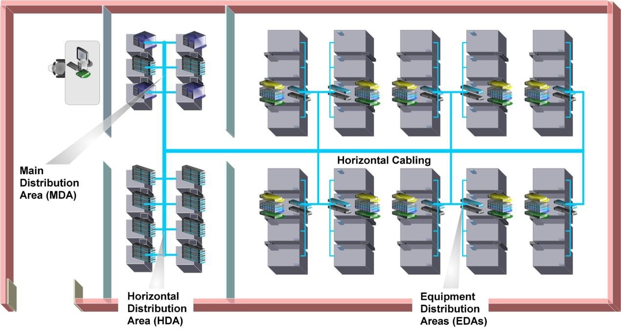
Data center network cabling design
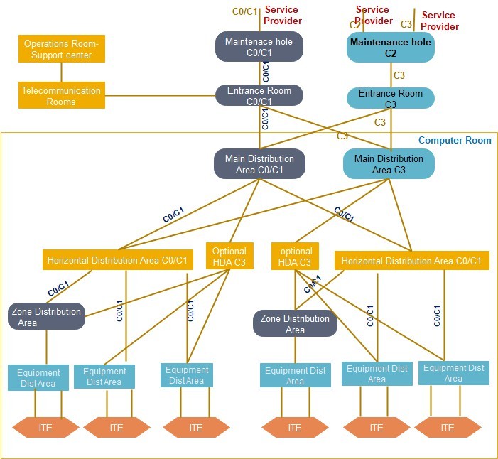
The datacenter cabling infrastructure layer contains, and the Data center spaces dedicated to supporting the telecommunications cabling system and related equipment are listed below. These spaces include:
- Entrance Room (ER)
- Main Distribution Area (MDA)
- Horizontal Distribution Area (HDA)
- Equipment Distribution Area (EDA)
- Zone distribution area (ZDA)
Data center telecommunications spaces such as the MDA and entrance room(s) shall be sized for full data center occupancy, including all anticipated expansions and planned applications.
All data center spaces for telecommunications shall have the same mechanical and electrical redundancy as the computer room(s). (Or even opposite) sides of the building.
Conduit duct banks and their associated maintenance holes and other pathways from the access provider central offices and service provider point-of-presences to the building’s entrance facilities should be separated by at least 20 m (66 ft.) along their entire routes.
A conduit duct bank with appropriately placed maintenance holes that surrounds a data center and incorporates multiple building entrance facilities should be considered for the data center.
At least one conduit for replacement cables should be set aside for each internal and entrance pathway to facilitate rapid replacement of cables.
The use of inner duct, either conventional or fabric, is recommended aiding in cable management and increased utilization of available conduit space.
Entrance Rooms
Access providers that serve the building shall be contacted to ascertain the point(s) of entry to the property and the requirements for their telecommunications cabling, terminations, and equipment.
Class C2 and higher data centers shall have diverse entrance facilities, preferably with route diversity from the data center to different access providers.
A Class C2 data center may be served from multiple central offices and multiple service provider point-of- presences that enter the property at different locations.
The location of each building entrance facility shall be coordinated with routing of access provider pathways as well as internal pathways and shall not conflict with the location of other building facilities such as power, gas, and water.
Each building point-of-entry supporting an access provider’s outside plant facilities should be located on different (or even opposite) sides of the building.
Conduit duct banks and their associated maintenance holes and other pathways from the access provider central offices and service provider point-of-presences to the building’s entrance facilities should be separated by at least 20 m (66 ft.) along their entire routes.
A conduit duct bank with appropriately placed maintenance holes that surrounds a data center and incorporates multiple building entrance facilities should be considered for the data center.
At least one conduit for replacement cables should be set aside for each internal and entrance pathway to facilitate rapid replacement of cables. The use of inner duct, either conventional or fabric, is recommended aiding in cable management and increased utilization of available conduit space.
When using multiple entrance rooms, entrance rooms should be at least 20 m (66 ft) apart and be in separate fire protection zones. The two entrance rooms should not share power distribution units or air conditioning equipment.
Telecommunications entrance cabling for data centers should not be routed through a common equipment room unless cabling is segregated from common access via conduit or other means.
Entrance rooms should be outside the computer room - to improve security. However, they may be placed in the computer room or consolidated with the main distribution area if cabling distances for circuits is an issue, security is not an issue, or other security measures are used to ensure security (such as escorting and monitoring the activities of all technicians in the computer room).
Main Distribution Area (MDA)
The MDA includes the main cross-connect (MC), which is the central point of distribution for the data center structured cabling system. The main cross-connect is called the main distributor (MD)
Equipment typically located in the MDA includes:
- Core routers
- Core, spine, or interconnection layer LAN and SAN switches
- High-performance computing switches
- PBX or voice gateways
- T-3 (M13) multiplexers
The MDA may serve one or more IDAs, HDAs, and EDAs within the data center and one or more telecommunications rooms (TRs) located outside the computer room space to support office spaces, operations center, and other external support rooms.
All data center shall have at least one MDA. A second MDA shall be provided to meet the availability requirements of the telecommunications infrastructure (e.g., Class C4). If two MDAs are present, both shall meet all requirements of the MDA as specified in the applicable data center standard.
Access provider provisioning equipment (e.g., M13 multiplexers) may be in the MDA rather than in the entrance room to avoid the need for a second entrance room because of circuit distance restrictions.
A second MDA is recommended in Class C3 data centers. Each MDA should have fully diverse cable routes to access multiple entry points so that no single point of failure exists within the site.
When utilizing two MDAs, the MDAs should:
- Have core routers and switches distributed between the MDAs
- Distribute circuits between the two spaces
- Be in different fire protection zones
- Be served by different power distribution units and air conditioning equipment
Intermediate Distribution Area (IDA)
The intermediate distribution area (IDA) is the space that supports the intermediate cross-connect. The intermediate cross-connect is called the intermediate distributor.
It may be used to provide a second level cabling subsystem in data centers too large to be accommodated with only MDAs and HDAs. The IDA is optional and may include active equipment such as LAN and SAN switches.
The IDA may include the horizontal cross-connect (TIA) or zone distributor (ISO/CENELEC) for equipment areas served directly from the IDA.
The IDA may be inside the computer room but can be located in a dedicated room or a secure cage within the computer room for additional security.
Horizontal Distribution Area (HDA)
The HDA is used to serve equipment not supported by a horizontal cross-connect (HC) or zone distributor
(ZD) in an IDA or MDA. The HDA is the distribution point for cabling to the EDAs. Equipment typically located in the HDA includes:
- LAN switches
- SAN switches
- Keyboard/video/mouse (KVM) switches
This equipment is used to provide network connectivity to the end equipment located in the EDAs. A small data center may not require any HDAs as the entire data center may be able to be supported from the MDA. A typical data center will have several HDAs.
Zone Distribution Area (ZDA)
The ZDA is an optional interconnection point within the horizontal cabling located between the HDA and the EDA to allow frequent reconfiguration and added flexibility.
The consolidation point in the ZDA is called the local distribution point or LDP in CENELEC EN 50173-5 and in ISO/IEC 24764.
Horizontal cabling shall contain no more than one ZDA between the HC in the HDA and the mechanical termination in the EDA.
The zone distribution area may also serve as a zone outlet for nearby equipment in the computer room.
Equipment Distribution Area (EDA)
The EDA is the space allocated for end equipment, including all forms of telecommunications equipment
(e.g., computer equipment, telephony equipment).
EDA areas shall not serve the purposes of an entrance room, MDA, IDA, or HDA.
Outside Plant Cabling Infrastructure
The data center site should have multiple duct banks with customer-owned maintenance holes from the property line to the data center.
The Duct banks should consist of a minimum of four 100 mm (trade size 4) or equivalent conduits or raceways. If initial plans include more than three access providers providing service to the facility, one additional 100 mm (trade size 4) or equivalent conduit or raceway should be provided for every additional access provider.
Each carrier’s cabling should be in separate, dedicated conduits or raceways. Carriers should not share
pathways.
The upper surface of underground cable pathways shall be no less than 600 mm (24 in) below the surface. Non-metallic conduits shall be encased in concrete with a minimum 17,000 kPa (2500 lb/sq in)
compressible Strength where there is vehicular traffic above or a bend in the conduits.
Cabling entrance pathways shall terminate in a secure area within the data center, The telecommunications entrance pathways shall be coordinated with other electrical underground pathways (e.g., conduits) and mechanical underground piping systems (e.g., water, waste) while maintaining appropriate pathway separation from physical and operational perspectives.
In regions susceptible to iciness, the top of the conduit(s) should be below the frost line. Where this is not practical, adequate protection should be provided to ensure that conduits do not become damaged as a result of ground shifting, particularly at the point of entry into the building.
Maintenance holes and hand holes on the data center property should have locks or other means of deterring access such as nonstandard bolts.
The maintenance holes and hand holes should have intrusion detection devices connected to the building security system and monitoring of the maintenance holes and hand holes by CCTV or other means.
Redundant duct banks should have a 20 m (66 ft) separation minimum along the entire route from the property line to the facility.
Where possible; redundant maintenance holes should relate to at least 100 mm (trade size 4) or equivalent conduit or raceway.
Conduits for cable replacement should be designated and marked separately from those for additional cables.
When multiple access providers are providing service to the facility, coordination of security requirements of each individual access provider should be within the secure space.
The secure area that houses the telecommunications entrance facility (pathway termination) should preferably be in a telecommunications entrance room that is separate from the computer room.
Any pull boxes or splice boxes for data center cabling (entrance cabling or cabling between portions of the data center) that are in public spaces or shared tenant spaces should be lockable. They should also be monitored by the data center security system using either a camera or remote alarm.
Entrance to utility tunnels used for telecommunications entrance rooms and other data center cabling should be lockable. If the tunnels are used by multiple tenants or cannot be locked, they should be monitored by the data center security system using either a camera or remote alarm.
Aerial Service Pathways
Routes for aerial access pathways shall follow same provisioning guidelines from an availability and security perspective as underground data pathways.
All aerial pathways shall be properly bonded and grounded, the use of aerial cabling pathways should generally be avoided because of vulnerability to outages. Aerial cabling route selection should take into consideration several factors, including, but not limited to, terrain, soil conditions, and aesthetics, proximity to direct-buried and underground utilities, access, and weather conditions.
Customer-owned satellite dish or aerial towers should be located within the secure perimeter of the facility.
Service Providers
Data center designers shall coordinate with all Service providers to determine their requirements and to ensure that the data center’s circuit, demarcation, and entrance facility requirements are provided to satisfy the access providers’ specifications.
Access providers typically require the following information when planning entrance facilities:
- Address of the building
- General information concerning other uses of the building, including other tenants
- Plans with detailed drawings of telecommunications entrance conduits from the property line to
the entrance rooms, including location of maintenance holes, hand holes, and pull boxes - Assignment of conduits and inner ducts to the access provider
- Floor plans for the entrance rooms
- Assigned location of the access providers’ protectors, racks, and cabinets
- Routing of cabling within entrance room (e.g., under access floor, over cabinets and racks, other)
- Expected quantity and type of circuits to be provisioned by the access provider, including any planned or foreseen additions or upgrades
- Media types and approximate distances of circuits to be provisioned by the carrier
- Service-level agreements
- Detailed schedules for the project, including date that the access provider will be able to install
entrance cabling and equipment in the entrance room and required service activation date - Requested location and interface for demarcation of each type of circuit to be provided by the access provider
- Carrier office diversity desired, preferably at least two separate access provider offices and service provider point-of-presences
- Carrier route diversity desired, preferably a minimum distance between any two routes of at least
20 m (66 ft.) along their entire routes - Specification of pathways to be used for access provider cabling (e.g., aerial cabling allowed or all underground)
- Type and rating of fire stopping measures used at the site
- Requested service date
- Name, telephone number, and e-mail address of primary customer contact and local site contact
- Security requirements for lockable containment and cabinets
- Colocation providers may be required to provide customer name and contact details if requesting on behalf of their customers
- Space and mounting requirements for protectors and terminations of balanced twisted-pair cabling
- Quantity and dimensions of access provider’s cabinets and racks or space requirements if they are to be provisioned in client cabinets and racks
- Power requirements for equipment, including receptacle types
- Access provider equipment service clearances
- Location of serving access provider central offices
- Route of access provider cabling and minimum separation between routes
- Specification on pathways used (e.g., all underground or portions of routes that are served by aerial cabling)
- Installation and service schedule
Application cabling lengths
The maximum supportable lengths in this annex are application and media dependent.
See below table in ANSI/TIA-568-C.0 for balanced twisted pair applications and table 7 in ANSI/TIA-568- C.0 for optical fiber applications.
T-1, E-1, T-3 and E-3 circuit lengths
Below table provides the maximum circuit lengths for T-1, T-3, E-1, and E-3 circuits with no adjustments for intermediate connections or outlets between the circuit demarcation point and the end equipment.
These calculations assume that there is no customer DSX panel between the access provider demarcation point (which may be a DSX) and the end equipment.
The access provider DSX panel is not counted in determining maximum circuit lengths.
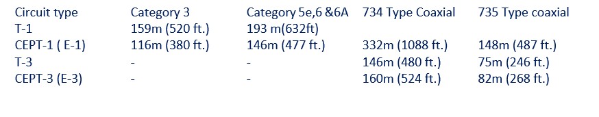
Repeaters can be used to extend circuits beyond the lengths specified above.
These circuit lengths should be adjusted for insertion- losses caused by a DSX panel between the access provider demarcation point (which may be a DSX panel) and the end equipment.
Maximum circuit lengths should be adjusted for insertion losses caused by intermediate connections and outlets.
Data center should have three connections in the backbone cabling, three connections in the horizontal cabling and no DSX panels between the access provider demarcation point and the end equipment.
Backbone cabling:
- one connection in the entrance room;
- Two connections in the main cross-connect;
- No intermediate cross-connect.
- Horizontal cabling:
- two connections in the horizontal cross-connect;
- An outlet connection at the equipment distribution area.
This “typical” configuration corresponds to the typical data center with an entrance room, main distribution area (MDA), one or more horizontal distribution areas (HDAs), and no zone distribution areas. Maximum circuit lengths for a typical data center configuration with six connections. These maximum circuit lengths should include backbone cabling, horizontal cabling, and all patch cords or jumpers between the access provider demarcation point and the end equipment.
Telecommunications Cabling Infrastructure Classes
For the telecommunications cabling infrastructure reliability classes, the corresponding class designation
is prefaced with a “C” to identify it represents the “cabling infrastructure” reliability criteria.
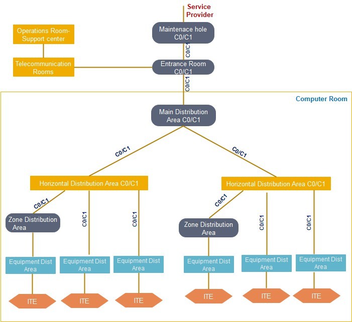
Class C0 and C1 Telecommunications Infrastructure
A Class C0 or C1 telecommunications cabling infrastructure is a single path cabling infrastructure. The cross-connect fields throughout the data center support a single path, non-redundant network architecture.
Entrance Pathways: Single path, multiple conduits from property line to
ER-Entrance Room: One ER accommodates a service provider
Main Distribution Area:
One MDA supports all core equipment
Intermediate Distribution Area
Each HDA supported by a single MDA or IDA Horizontal Distribution Area:
Non-redundant HDA to support any intermediary switching equipment and horizontal cross-connect fields, multiple HDAs may be required to support port counts and distance limitations within large computer rooms.
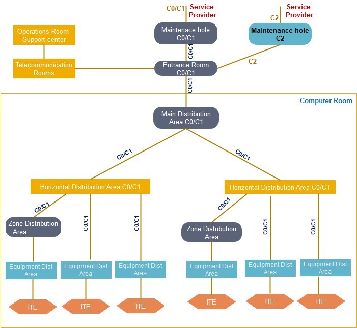
Class C2 Telecommunications Infrastructure
A Class C2 telecommunications cabling infrastructure is a single path cabling infrastructure. The cross- connect fields throughout the data center support a single path, non-redundant network architecture. It contains redundant entrance pathways to support, at a minimum, a single link from two providers or ringed topology from one provider.
Entrance Pathways: Redundant and diverse multi-path, each path with multiple conduits from property line to ER.
Entrance Room: One ER accommodates a service provider(s) Main Distribution Area: One MDA supports all core equipment
Intermediate Distribution Area Each HDA supported by a single MDA or IDA
Horizontal Distribution Area: Non-redundant HDA to support any intermediary switching equipment and
horizontal cross-connect fields, multiple HDAs may be required to support port counts and distance limitations within large computer rooms.
Class C3 Telecommunications Infrastructure
A Class C3 telecommunications cabling infrastructure is a redundant path cabling infrastructure that has redundant cross-connect fields for all backbone network cabling.
The redundant backbone cabling is intended to support a redundant network.
Physically separated redundant horizontal cross-connects and a redundant horizontal cabling to equipment cabinets (EDAs) is also recommended.
Physical separation between redundant MDAs, IDAs, or HDAs may minimize common modes of failure that may be present within the supporting critical infrastructure (e.g., failure of the sprinkler system, raised floor system, cabling pathway system, grounding system).
Physical separation may also minimize failure because of any event caused by human error or component failure, which is not contained within an MDA or HDA cabinet, thereby exposing adjacent cabinets to risk of failure.
Having redundant distributors and cabling may increase operational complexity.
Entrance Pathways: Redundant and diverse multi-path, each path with multiple conduits from property line to each ER.
Entrance Room: Two ERs to support multiple service providers, providing physical separation between
Redundant provider and edge equipment.
Main Distribution Area: MDAs support the main cross-connect (MC) and backbone network equipment. Redundant MDAs should be physically separated.
Intermediate Distribution Area IDAs support the intermediate cross-connect (IC) and possibly backbone network equipment. Redundant IDAs should be physically separated.
Horizontal Distribution Area: HDAs support horizontal cross-connects and may support access layer
switches.
Equipment cabinets (EDAs) should (but are not required to) have horizontal cabling to two different, physically separated HDAs.
Class C4 Telecommunications Infrastructure
A Class C4 telecommunications infrastructure is a redundant path cabling infrastructure that has redundant cross-connect fields throughout data center network to support redundant network architecture. It contains redundant entrance facilities to support multiple network service provider topologies.
Physical separation between redundant MDAs or HDAs is required to minimize common modes of failure that may be present within the supporting critical infrastructure (e.g., failure of; sprinkler system, raised floor system, cabling infrastructure pathway system, grounding system, electrical distribution system) or any event caused by human error or component failure, which is not contained within one MDA or HDA cabinet, thereby exposing adjacent cabinets to risk of failure as well.
Entrance Pathways: Redundant and diverse multi-path, each path with multiple conduits from property line to each ER
Entrance Room: Two ERs to support multiple service providers, providing physical separation between redundant providers edge equipment.
Main Distribution Area: Two MDAs to support redundant core equipment. Physical separation between redundant MDAs is required to minimize common modes of failure that may be present within the supporting critical infrastructure.
Intermediate Distribution Area Redundant physically separated IDAs. If an HDA has backbone cabling to
IDAs, it must be supported by diversely routed backbone cabling to two physically separated IDAs.
Horizontal Distribution Area: Redundant HDAs to support any intermediary redundant switching equipment and horizontal cross-connect fields, additional HDAs may be required on both the “A” and
“B” network fabric to support increased port counts and distance limitations within large computer rooms.
Physical separation between redundant HDAs is required to minimize computer common modes of failure that may be present within the supporting critical infrastructure

Cabling Topology
The basic cabling elements of the data center star topology should include:
- Horizontal cabling
- Backbone cabling
- Equipment cabling
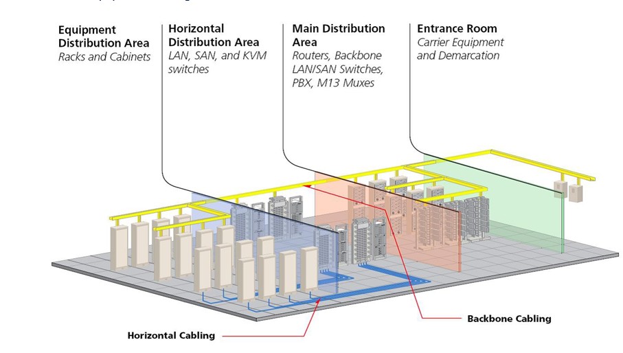
Horizontal cabling
The system of cabling that connects telecommunications rooms to individual outlets or work areas on the floor.
In premise cabling, any cabling that is used to connect a floor’s wiring closet to wall plates in the work areas to provide a local area network (LAN) drops for connecting users’ computers to the network.
Backbone cabling
Backbone cabling systems provide necessary interconnects at the datacenter facility, providing the vital cabling foundation to datacenter stay connects with inside and outside of facility.
It Connects between MDA, IDA, HDA room and entrance section in the datacenter, Backbone cabling consists of the transmission media, main and intermediate cross-connects and terminations at these locations.
The presence of an HDA or IDA is not mandatory. Cabling extending from the TIA HC in the HDA, IDA, or MDA to the mechanical termination in the EDA is considered horizontal cabling. Sufficient horizontal cable slack should be considered allowing migration to a cross-connect in the HDA, IDA, or MDA. Backbone cabling cross-connects may be in TRs, computer rooms, MDAs, IDAs, HDAs, or at entrance rooms.
Equipment cabling
Equipment cabling connects the cable from one device to another device and this type of cabling occurs inside the cabinet and rack.