Data Center Cabling Pathways
Datacenter should ensure that capacity of pathway has been estimated as per quantities cable when the data center is fully populated, and all expansion areas are built.
Cabling pathway design should have an adequate capacity of pathways at entrance rooms, main distribution areas (MDAs), intermediate distribution areas (IDAs), horizontal distribution areas (HDAs), and intersections of cabling pathways.
Data centers cabling should not be routed through spaces accessible by the public or other neighbors and make sure that cables are enclosed conduit or other secure pathways.
All maintenance holes; pull boxes or splice boxes should be equipped with a lock and entrance cabling for data center should not be routed through a common equipment room and it should be a monitored datacenter security system using a camera or remote alarm.
Utility tunnels used for datacenter entrance rooms should be keep locked, if tunnels are shared with other data centers, it has to be in good metallic conduit or secure pathway separation.
Ensure that there is a proper distance between power cables and balanced twisted-pair cables as per ANSI/TIA 569 C Standards and there should be horizontal and vertical separation of power and network cables.
Make sure that different rows of tiles in the main aisles for power and network cabling. Provide vertical separation by placing network cabling in cable trays or baskets.
Twisted pair cable must be separated from fiber if used in same pathways. Cords and jumpers should be separated from other cabling.
Telecommunications pathways for datacenter should pass through underground and overhead pathways are not recommended. The entrance pathways should also have adequate capacity to handle growth and additional access providers.
- Cable Tray Support Systems
- Overhead Cable Trays
- Underfloor Cable Trays
- Backbone Cabling
- Cabling Types
- Cabling Installation
- Telecommunications and Computer Cabinets and Racks
- Cabinet Airflow and Cabling Capacity
- Cabinet and Rack Installation
- Thermal Management in Cabinets
Cable Tray Support Systems
Each access provider should have at least one metric designator 103 (trade size 4) conduit at each entrance point.
Additional conduits may be required for campus cabling. Conduits used for optical fiber entrance cables should have three inner ducts [two metric designator 40 (trade size 1.5) and one metric designator 27 (trade size 1) or three metric designator 32 (trade size 1.25)]. Consider the use of soft-sided duct material as a substitute for inner duct, which may optimize the use of finite conduit cross-sectional area.
All cables should be tied and labeled, and cables shall not be left abandoned under the access floor. Cables shall be terminated on at least one end in the MDA or an HDA or shall be removed.
Overhead Cable Trays
In data centers that use overhead pathways, 150 mm (6 in) minimum access headroom shall be provided from the top of the pathway to the obstruction located above such as another pathway or the ceiling. This clearance requirement does not apply where cable trays cross each other or cross beams, pipes or other building structures.
Typical cable tray types for overhead cable installation include wire basket cable tray, ladder type, or center spine cable tray. Adjacent sections of metallic cable tray shall be bonded together and grounded per manufacturers’ guidelines, /NECA/BICSI 607, other applicable standards (e.g., TIA-607-B), and the local authority and shall be listed or classified by an NRTL for this purpose.
The metallic cable tray system shall be bonded to the data center common bonding network.
When they are supported from above; overhead cable ladders or trays (if used) shall be suspended from the structure above utilizing M12 (0.5 in) or greater threaded rods as required for structural support.
The cable trays or ladders may be supported by an overhead support structure using support pillars or a suspended frame designed to support the load of the cable tray and cables.
If used for seismic bracing, ladder racks and cable tray shall be continuous wall to wall to form a brace for the equipment.
Cable tray shall not be routed directly below fire suppression or sprinkler systems.
In data centers that use overhead pathways, 300 mm (12 in) minimum access headroom should be provided from the top of the pathway to the obstruction located above such as another pathway or the ceiling.
Underfloor Cable Trays
Ensure that necessary airflow is passing under the access floor it has to be properly ventilated. Refer
ANSI/TIA-569-C for further cable tray design considerations.
Under floor cable trays may be installed in multiple layers to provide additional capacity. Metallic cable tray shall be bonded to the data center grounding infrastructure. The cable tray should have a maximum depth of 150 mm (6 in).
To provide room for cables to exit the pathways, there shall be a minimum of 20 mm (0.75 in) from the bottom of the access floor tiles to the top of the cable tray and cabling in a cable pathway that is loaded
100% of calculated capacity.
Under floor systems that require periodic access or maintenance of such as valves, electrical receptacles, and smoke detectors should not be located below under floor cable pathways unless there is an empty row of tiles adjacent to these pathways.
Under-floor cable tray routing should be coordinated with other under floor systems during the planning stages of the building.
Planning of overhead cable trays for telecommunications cabling should be coordinated with architects, mechanical engineers, electrical engineers, and plumbing and structural engineers that are designing luminaries, plumbing, and HVAC, power, and fire protection systems. Coordination should consider routing, clearances, and accessibility; consider use of three-dimensional drawings to simplify coordination.
Lighting fixtures (luminaries) and sprinkler heads should be placed between cable trays, not directly above cable trays.
Overhead cable trays should be routed to avoid impeding airflow, sprinkler patterns, and lighting. This typically implies routing cable trays over cabinets and racks rather than above aisles between them.
Overhead cable tray systems may alleviate the need for access floors in data centers that do not employ floor-standing systems that are cabled from below.
Typical installations include two or three layers of cable trays, one for power cables and one or two for cabling.
One of the cable tray layers may employ brackets on one side that hold the data center grounding infrastructure. These overhead cable trays may be supplemented by a duct or tray system for fiber patch cables. The fiber duct or tray may be secured to the same hanging rods used to support the cable trays.
Cable pathways should not be located where they interfere with proper operation of fire suppression systems such water distribution from sprinkler heads.
Overhead cable pathways should not block airflow into or out of cabinets (e.g., not block air exiting the hot aisle or cabinet vents if located at the top of cabinets).
Cables should not be left abandoned in overhead cable trays. Cables shall be terminated on at least one end in an MDA, IDA, or HDA, or shall be removed.
In aisles and other common spaces in internet data centers, co-location facilities, and other shared tenant data centers, overhead cable trays should have solid bottoms or be placed at least 2.7 m (9 ft) above the finished floor to limit accessibility or be protected through alternate means from accidental and/or intentional damage.
The maximum recommended depth of cable in any cable tray is 150 mm (6 in). Typical cable tray types for overhead cable installation include policy-type cable ladders, center spine cable tray, or wire basket cable tray. The cable tray system shall be bonded and grounded per ANSI/TIA-607-B.
Overhead cable trays should be suspended from the ceiling. Where building structural characteristics make overhead suspension of a cable tray impossible, the tray can be suspended from a structural grid that is supported by other means. If all racks and cabinets are of uniform height, the cable trays may be attached to the top of racks and cabinets, but this is not a recommended practice because suspended cable trays provide more flexibility for supporting cabinets and racks of various heights and provide more flexibility for adding and removing cabinets and racks.
Lighting fixtures and sprinkler heads should be placed between cable trays, not directly above cable trays. Cable trays should be located above cabinets and racks instead of above the aisles where lighting should
be located.
Access flooring shall meet the performance requirements of ANSI/TIA-569-C. Access floors for data centers should use a bolted stringer understructure as they are more stable over time than stringer less systems. Additionally, access floor stringers should be 1.2 m (4 ft) long installed in a “basket weave” pattern to improve stability.
Pedestal adhesive should be applied under all base plates. Pedestal bases should also be bolted to the subfloor (except post-tension floors) for added stability in seismic areas.
Access floor tile cuts should have edging or grommets along all cut edges. If the edging or grommets are higher than the surface of the access floor, they shall be installed as not to interfere with placement of racks and cabinets.
The edging or grommets shall not be placed where the racks and cabinets normally contact the surface of the access floor.
In the case of down-flow AC systems where the access flooring is being used as an air distribution plenum, floor tile cuts should be limited in both size and quantity to ensure proper airflow.
Floor tiles with cement or wood cores should have their exposed cut edges sealed in order to prevent core material from being blown into the computer room.
After cuts are made to the access floor system and all equipment racks, cabinets, etc. are in place, it is recommended that the AC system be properly balanced.
Backbone Cabling
The function of the backbone cabling is to provide connections between the MDA, IDA, HDA, and entrance rooms in the data center cabling system.
Backbone cabling consists of the backbone cables, MC/MD, IC/ID, mechanical terminations, equipment cords, and patch cords or jumpers used for backbone-to-backbone cross-connection.
The backbone cabling shall allow network reconfiguration and future growth without disturbance of the backbone cabling.
Cabling Types
Each recognized cable has individual characteristics that make it suitable for a range of applications defined against each category or cabling type in the applicable cabling standards.
A single cable may not satisfy all end user requirements. It may be necessary to use more than one medium in the backbone cabling.
In those instances, the different media shall use the same facility architecture with the same location for cross-connects, mechanical terminations, and inter-building entrance facilities.
As a result of the wide range of services and site sizes where backbone cabling will be used, more than one transmission medium is recognized.
This standard specifies the transmission media that shall be used individually or in combination in the backbone cabling.
Recognized cables associated connecting hardware, jumpers, patch cords, equipment cords, and zone area cords shall meet all applicable requirements specified in applicable standards and related addenda (e.g., ISO/IEC 11801, TIA-568-series).
Backbone cabling shall consist of one or more of the following media types:
• 100-ohm balanced twisted-pair Category 3/Class C minimum, (Category 6/ Class E or higher recommended)
• OM3 multi-mode optical fiber cable minimum, (OM4 multi-mode optical fiber cable recommended)
• OS1 or OS2, single-mode optical fiber cable
• 75-ohm coaxial cabling (Telcordia GR-139-CORE 734-type and 735-type)
Redundant backbone cabling protects against an outage caused by damage to the primary backbone cabling.
Redundant backbone cabling may be provided in several ways, depending on the degree of protection desired.
Backbone cabling between two spaces (e.g., a horizontal distribution area and a main distribution area)
can be provided by running two cabling channels between these spaces, preferably along different routes.
If the computer room has two main distribution areas, redundant backbone cabling to the horizontal distribution area may not be necessary although the routing of cabling to the two main distribution areas should follow different routes.
Some degree of redundancy can also be provided by installing backbone cabling between horizontal distribution areas. If the backbone cabling from the main distribution area to the horizontal distribution area is damaged, connections can be patched through another horizontal distribution area.
The Equipment cords and patch cords, the backbone cabling distances shall be designed to accommodate the maximum cordage length so that when configuring channels for use with applications the combination of equipment cord, a permanent link and patch cords never exceeds the channel loss limits.
Centralized Optical Fiber Cabling
Centralized optical fiber topologies permit the intermediate distribution areas and horizontal distribution areas to have no switches.
Centralized cabling design shall allow for the addition and removal of horizontal and backbone optical fiber cabling.
Enough space shall be left in the HDA and IDA to allow for the addition of patch panels needed for the migration of the pull-through, interconnect, or splice to a cross-connection.
Centralized cabling design shall allow for migration (in part or in total) of the pull-through (continuous sheath cables), interconnect, or splice implementation to a cross-connection implementation or configuration utilizing equipment (e.g., switches) in the distributors.
Centralized cabling shall support the administration and labeling requirements of the cabling standards being followed.
Administration of moves and changes shall be performed at the centralized cross-connect. In addition, computer room splice, and interconnect hardware shall be labeled with unique identifiers on each termination position.
Polarity shall adhere to the requirements of the cabling standards being followed. Service loop storage shall provide bend radius control so that optical fiber bend radius limitations are not violated.
Single-Mode and Multimode Connector Color Recommendations
The single-mode connector or a visible portion of it should be blue, referring to a flat-polished optical fiber end face; green should signify a connector featuring an angle polished optical fiber end face.
Where a mixture of OS1 and OS2 exist in a single data center space or room, additional identification should be applied to clearly identify the fiber type used.
Horizontal Cabling
The horizontal cabling is the portion of the telecommunications cabling system that extends from the equipment outlet (EO) in the EDA to the TIA HC or ISO/CENELEC ZD in an HDA, IDA, or MDA.
The horizontal cabling includes:
- Horizontal cables
- Mechanical terminations
- Equipment cords, patch cords, or jumpers;
- TIA zone outlet, TIA consolidation point (CP), or ISO/CENELEC local distribution point (LDP) in the optional ZDA
Horizontal cabling shall consist of one or more of the following media types:
- 4-pair 100-ohm balanced twisted-pair Category 6/Class E minimum (Category 6A/Class EA or higher recommended)
- OM3 multi-mode optical fiber cable minimum (OM4 multimode optical fiber cable recommended where horizontal fiber cabling lengths exceed 70 m [230 ft])
- OS1 or OS2, single-mode optical fiber cable
Balanced Twisted-Pair Cabling
Balanced twisted-pair cabling performance is described using a scale based on classes or categories, as defined by ISO/IEC and TIA, respectively. While Category 3/Class C is the minimum acceptable performance for backbone cabling, Category 6/Class E is the minimum requirement in TIA-942-A and CENELEC EN 50173-5 for horizontal cabling, and Category 6A/Class EA is the minimum requirement as listed in ISO/IEC 24764.
Cabling Installation
Cabling shall be installed and dressed neatly, taking care to adhere to minimum cable bend radii for cables. Take particular care not to leave excess optical fiber loops on the floor or in places where they can be damaged. While all transmission parameters are sensitive to transmission discontinuities caused by connector terminations, return loss, and all forms of crosstalk (e.g., near-end crosstalk [NEXT], attenuation-to-crosstalk ratio–far end[ACR–F], previously known as ELFEXT), performance of balanced twisted-pair systems are particularly sensitive to conductor untwisting and other installation practices that disturb pair balance and cause impedance variations.
To prevent these problems, the installer shall adhere to the following practices:
- Remove only as much cable jacket as is required for termination and trimming.
- Follow the manufacturer’s instructions for mounting, termination, and cable management.
- Minimize the amount of untwisting in a pair as a result of termination to connecting hardware. For untwisting cabling, maintain pair twists as close as possible to the termination point; the amount of untwisting must not exceed 13 mm (0.5 in) for Category 5e and higher cables.
Telecommunications and Computer Cabinets and Racks
As with all other systems of the data center—power, HVAC, and flooring—cabinets and racking systems provide the vital services of proper structural and secure housing for data center equipment. Active and passive equipment have different requirements for mounting, power, ventilation, and cable management.
The following criteria of racks shall conform to applicable codes, standards and regulations (e.g., EIA/ECA-
310-E, IEC 60917):
- Channel dimensions and spacing
- Channel hole dimensions and thread systems
- Channel equipment mounting hole vertical spacing (U or RU)
- Panel opening and usable aperture opening
Maximum height should not exceed 2.4 m (8 ft.)
When in a row, multiple racks and their associated vertical cable managers should be bolted together
The following criteria shall conform to applicable codes, standards, and regulations (e.g., EIA/ECA-310-E, IEC 60917):
- Equipment mounting rail dimensions and spacing
- Equipment mounting rail hole vertical spacing (U or RU)
- Options for cable access into the cabinet shall be available from both the top and bottom.
- Access floor openings beneath cabinets for cable entry shall offer:
- Protection against damage to the cables
- Restrictions against intrusion of dirt and debris
- Restriction of air passage
- Cabinets shall be constructed of noncombustible materials.
Top access ports should provide a means to be closed when not in use.
In seismically active areas, multiple cabinets in a row should be bolted together at the top to provide additional Stability.
Within EDAs, select cabinets, racks, and vertical cable managers whose design minimizes obstruction of exhaust air and recirculation of hot air from behind the equipment to air intakes in the front of the equipment.
Within HDAs, IDAs, and MDAs, select cabinets, racks, and vertical managers whose design optimizes patch cord management, while minimizing air leakage between hot aisle and cold aisle.
In data centers that employ hot aisle/cold aisle orientation, ensure that the warm air is always exhausted toward the hot aisle.
Optical fiber and balanced twisted-pair ports are located at the rear of many servers.
To simplify patching and maintenance, structured cabling patch panels should be mounted so that the ports face the same direction as the network ports on the equipment to which they are patched. These ports are commonly on the rear of servers and the front of network switches.
For equipment that is cooled side-to-side (e.g., certain networking equipment), cabinets, racks, and vertical cable managers should be selected that introduce the least disruption to the proper functioning of the hot and cold aisles and that minimize recirculation of hot air toward the air intakes.
Finishes should conform to applicable codes, standards, and regulations (e.g., ANSI/TIA-942-A, ATIS
0600336);
Conductive finishes are recommended to ensure a good bond between equipment and cabinet or rack ground and to prevent oxidation of the base metal.
For painted racks, a supplementary bonding/grounding bus bar system may be used to ensure a good bond between equipment and cabinet or rack ground.
Cabinet and rack bonding and grounding should comply with applicable codes, standards, and regulations
(e.g., NECA/BICSI-607, TIA-607-B, and ISO/IEC DIS 30129 currently in development).
Racks in entrance rooms, main distribution areas and horizontal distribution areas should have dimensions and cable management capacities in accordance with applicable codes, standards, and regulations (e.g., TIA-942-A).
Twisted pair or coaxial patch panel should be used unless a specific high-density solution of managing the patch cords on the sides for every unit is chosen.
Exceptions exist when a non-angled patch panel features an integrated horizontal management product design.
Vertical cable management should always be provided unless patching is provided directly above or directly below mated passive patch panels (e.g., balanced twisted-pair, coaxial cabling, or optical fiber cabling) or between passive patch panels and active equipment that are installed directly above or below one another.
In such cases, relatively short (typically less than 1 m [3 ft.] patch cord assemblies (or equipment cord assemblies) may be used. When angled patch panels are used, horizontal cable managers are typically not installed.
Vertical cable managers should always be sized to accommodate the anticipated maximum cordage that may be deployed given the equipment requirements at the time of deployment.
Shorter power cords, equipment cords, patch cords, and keyboard-video-mouse (KVM) cabling should be specified to reduce the cable management density in the back of the cabinet or rack.
Rack depth should meet the mounting and protection needs of the equipment they are to host and, as a minimum, conform to the criteria established in applicable standards (e.g., EIA/ECA-310-E, IEC 60917).
Each rack should have vertical cable managers sized for maximum rack capacity attached on both sides. Vertical cable managers between two racks should be sized to serve both racks simultaneously.
Equipment mounting rails should be adjustable front-to-rear and should have rack unit number indications (with numbers starting at the bottom).
Equipment mounting rail dimensions should conform to applicable codes, standards, and regulations (e.g., EIA/ECA-310-E, IEC 60917).
Doors should be removable without tools. Door hinge orientation should be reversible or dual hinged. Side panels should be removable and lockable without requiring intrusion into the equipment mounting
area within the cabinet.
In applications where active equipment, patch panels, and horizontal cable distribution are mixed, floor- tile-width (e.g., 600 mm [24 in] width) cabinets may lack adequate vertical cable management space.
Blank panels should be installed in unused rack positions to maintain separation between hot aisles and cold aisles and prevent hot exhaust air from recirculating and mixing with chilled air at equipment in- takes. Blank panels also improve rigidity of cabinets.
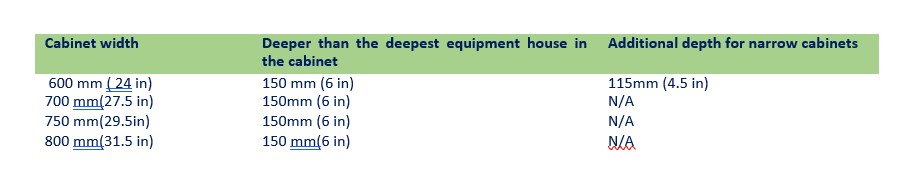
Cabinet Airflow and Cabling Capacity
To ensure adequate airflow and to provide adequate space for power strips, telecommunications cabling, and safe access for work, the cabinet depth should be at least 150 mm (6 in) deeper than the deepest equipment to be housed if the cabinet is 700 mm (27.5 in) wide or larger.
If the cabinet is less than 700 mm (27.5 in) wide, 11.5 mm (0.45 in) depth should be added for every 10 mm (0.4 in) reduction from 700 mm (27.6 in) width.
Mesh doors are used for ventilation, the doors should be a minimum 63% open to airflow for allowing chilled air entrance or evacuating heated exhaust air from the cabinet.
It is recommended that the following formulae be used to calculate door airflow capacity: Airflow capacity (AFC) calculations:
AFCD = SD × FEA
AC × HRMU × NRMU (14-4)
Where:
AFCD is airflow capacity for cabinets with doors SD is total surface area of the door panel inside the outer extreme boundaries of airflow openings (mesh, perforations, slots, etc.), in mm2 (in2) FEA is effective (open) area factor of the door mesh material (e.g., 0.65 [65%], 1 if mesh or screen is not used)
AC is useable cabinet aperture opening at the door plane, in mm (in) HRMU is height of one rack unit (44.5 mm [1.75 in])
NRMU is quantity of rack units in the cabinet.
Given:
- 19-in equipment cabinet
- Height: 42 RMU
- Mesh door with FEA = 0.65, 1,930 mm x 635 mm (76 in x 25 in)
- 1 RMU = 44.5 mm (1.75 in)
- Cabinet open aperture: 450.85 mm (17.75 in)
NOTE: Input data and criteria used in the examples above are provided as samples only. For actual parameters, please refer to the particular network cabinet or server cabinet design requirements.
Airflow capacity:
AFCD = (SD × FEA) = (1,930 mm × 635 mm × 0.65) AC × HRMU × NRMU 450.85 mm × 44.5 mm × 42
AFCD = 1,225,550 mm2 × 0.65 842,639 mm2 = 0.9454
Cabinet and Rack Installation
Where the cabinets and racks are on an access floor, they shall be placed so that there are movable tiles in front and behind each cabinet and rack.
This typically means placing the rows of cabinets and racks parallel (rather than at an angle) to the rows of floor tiles and placing the front edge of the cabinets along the edge of the floor tiles to lock down the minimum number of tiles under the cabinets
All overhead cable management (e.g., ladder racks, cable tray, etc.) shall remain free of obstructions such as sprinklers, lighting, and electrical outlets.
The designer shall anticipate the weight of the equipment in the cabinets and racks; ensure that the cabinets, racks and floors (both access floors and slabs) are rated to handle the expected weight.
Adequate power shall be available to all cabinets and racks that will hold active equipment and must be installed in accordance with applicable codes.
Each cabinet and rack shall be labeled on the front and back with its identifier. All patch panels, cables, equipment cords, and patch cords shall be properly labeled per applicable standards (e.g., TIA-606-B, ISO
14,763-2-1).
Cabinet and rack layout designs should be harmonized with lighting (luminaire) delivery layout designs. Anticipate growth and leave room for expansion when/if possible.
Power strips should be labeled with power distribution unit or electrical panel board identifier and circuit breaker number.
Power cords should not be installed under equipment, mats, or covering other than access floor tiles.
The mounting surface for cabinet and racks should be prepared for the specific anchors required for the application.
Cabinets in a line-up where they are properly attached together may require fewer anchors per cabinet than those installed as standalone units.
When drilling into the mounting surface use proper technique to ensure that dust or particles do not get airborne. Using a drill with the attached vacuum is an effective way to prevent dust or particles while drilling in floors or walls.
Equipment in the computer room should be mounted to cabinet or rack rails rather than placed on directories as equipment on directories provides a return path for air between the rear and front of the cabinet or rack.
Floor tile openings under cabinets and racks should be no larger than required for entry of cabling to minimize loss of underfloor pressure through openings.
Consider using openings with gaskets or brush grommets to satisfy requirements to minimize air pressure loss and short-circuiting of cold aisle/hot aisle air circulation and subsequent reduction in cooling efficiency.
A dedicated pathway should be provided for equipment cords or patch cords within an MDA, IDA, or HDA
that is separate from those used for horizontal and backbone cabling.
Ensure all active devices are properly supported and securely mounted to the rack to prevent equipment damage from improper installation.
In seismically active areas, it is recommended that the design of the attachment methods and the installation be reviewed by a licensed structural engineer. Many jurisdictions will require a seismic certification report signed by a professional engineer.
Sharp edges at the top of the threaded rods should be capped (using plastic covers, domed nuts, or other means).
The exposed threads under the access floor should be covered using split tubing or other method to avoid abrading cable.
Racks should be set in place and leveled throughout the line-up.
Shimming of any anchoring point should not exceed 13 mm (0.5 in) unless specified by the project engineer. If racks require more than 13 mm (0.5 in) of shimming, an engineered solution should be used to ensure rack line-ups are properly supported.
Adjacent racks in the line-up should be hanged together before anchors are installed. Install anchors per manufacturer specification, making sure all shims are properly located.
Some line-ups require additional bracing to meet customer specifications or local codes. Required bracing may be based on rack style, equipment, and location.
Bracing should be installed as a system to ensure proper fit and support. Install all parts hand tight and then tighten fasteners in a series to prevent stress on rack lineup. All bracing should be installed before racks are populated.
Avoid empty cabinet or rack positions in rows.
Replace removed cabinets or frames and fill any gaps in a row of cabinets with a substitute blanking panel of the same height as the cabinet or frames to either side to avoid recirculation of air between hot and cold aisles.
Cabinets and racks should be installed with no blank spaces between them. In the case of vacant cabinets and racks and where blank spaces exist in populated cabinets and racks, install blanking panels.
Vertical cable managers can provide cable management and block recirculation of air between racks. Cabinets should be butted up against each other. Where possible, bayed cabinets should still share a side
panel or include other means to seal the rear-to-front airflow path along the side of rack-mounted equipment.
Placing one edge of the cabinet creates unequal aisle sizes, the front aisle should be the larger one as it provides more working space for installation of equipment into cabinets and a greater area for providing cool air to cabinets.
In order to meet the requirement to restrict air passage through all openings outside the cold aisle on access floors, floor tile openings under cabinets and racks should be no larger than required for entry of cabling to minimize loss of underfloor pressure through openings considering anticipated growth.
Consider using openings with gaskets or brush grommets to minimize air pressure loss and short-circuiting of cold aisle/hot aisle air circulation and subsequent reduction in cooling efficiency.
Ensure that all active devices are properly supported and securely mounted to the cabinet to prevent equipment damage from improper installation.
Plan equipment; power strip, cable manager, and cabling layouts in cabinets before making a major purchase.
Either create detailed drawings or preferably create a mock up to ensure that:
- All equipment and cable managers fit properly
- There is adequate space and access to power strips
- There is adequate access to cabinet floor and top openings
- There is adequate space for cable management
- Equipment can properly slide in and out as required
- Equipment intakes and exhausts are not blocked by cabling, cable management, or cabinet structure so that air can flow freely within the rack and to exit out the hot side
- Cabinets, racks, and vertical management do not have large openings for recirculation of air from
hot to cold aisles temporarily remove any doors and panels that may interfere with the cabinet installation.
On solid or slab floors, cabinets should be set in place and leveled throughout the line-up. Most cabinets are equipped with leveling feet. If leveling feet are not provided, consult manufacturer for proper shimming hardware.
On access floors, cabinets and racks should be secured to the concrete subfloor. If cabinets in the line-up are to be hanged, attachment hardware should be installed before anchors are installed. Install anchors per manufacturer’s specification, making sure all shimming hardware is properly located.
In seismically active areas, it is recommended that the design of the cabinets and their installation be reviewed by a licensed structural engineer as many jurisdictions require a seismic certification report signed by a professional engineer.
Sharp edges at the top of the threaded rods should be capped (using plastic covers, domed nuts, or other means).
The exposed threads under the access floor should be covered using split tubing or other method to avoid abrading cable.
Floor tile panels should have correctly sized and placed cutouts for the cabinet or equipment placed over them.
The cutout should be under the cabinet/equipment cord opening and properly sized for the quantity and type of cables to be routed through the opening.

Thermal Management in Cabinets
There is no one thermal management configuration that works best in every instance. Each may be optimal, depending on different factors unique to the customer, application, and environment.
Consideration should be given to understanding the upfront installed costs as well as an ongoing operational cost from an energy efficiency and maintenance perspective.
Equipment should be installed in cabinets with the air intake oriented toward the front of the cabinet or rack and the air exhaust oriented toward the rear of the cabinet or rack, when possible, with the cabinet rows oriented in a “hot aisle/cold aisle” configuration—rears of cabinets facing each other and fronts of cabinets facing each other.
Use of any supplementary cooling mechanisms on a cabinet must take into consideration its effect on the overall fluid dynamics of the air space and how other equipment will be affected.
Considerations of supplemental cooling systems need to include criticality and required levels of redundant backup.
Cabinets with good passive air management systems in well-designed rooms remove concerns about single points of failure and can support heat loads of twenty kW and higher.
Cabinet fans for cabinets specially designed to handle high heat loads should be on UPS power and have redundant power cords or be on transfer switches to ensure continuous operation.
Cabinet fans should be on separate circuits from the equipment in the cabinet as fans are susceptible to ground faults.
The perimeter of the equipment mounting area is also a path for cold air bypass or hot air recirculation and should be blocked accordingly.
Careful planning is needed for capacities, heat loads, and redundancies required for the desired availability and reliability.